
Page 280 - Forensic Structural Engineering Handbook
P. 280
8.20 CAUSES OF FAILURES
provide adequate protection of roofing members from interior and exterior environmen-
tal conditions. Exposure of wood framing to the elements during construction can also
contribute to significant issues. For example, warping of floor sheathing and rusting of
fasteners can be caused by exposure to rain during construction.
• Long-term creep deflections, caused by water ponding, design of support for roof-top
equipment replacement/addition and installation frequently results in construction- and
design-related deficiencies.
Invasively determining the cause of defects is most readily accomplished in wood
framed structures due to the relative ease of removal and replacement of construction mate-
rial. However, nondestructive methods, such as the elementary use of magnets to locate and
quantify the number of fasteners securing sheathing elements to interior walls; or mildly
invasive methods such as a boroscope or moisture meter can provide an effective substitute
to the more invasive methods. Typically the effect of deficiencies, discovered during a
forensic evaluation, on the structure’s load carrying capacity must be analyzed.
Masonry Structures
Construction using concrete masonry units (CMU) is prevalent in the building industry.
Regional practices and applicable design codes greatly influence the design and construc-
tion of such CMU walls. Other than poor workmanship, the most commonly encountered
deficiencies in CMU construction are
• Improper placement of reinforcement within concrete masonry unit cells
• Inadequate or absent grouting of concrete masonry unit cells
• Concrete masonry unit walls not designed to resist out-of-plane loads
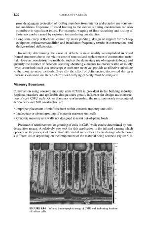
Presence of reinforcement or grouting of cells in CMU walls can be determined by non-
destructive means. A relatively new tool for this application is the infrared camera which
operates on the principle of temperature differential and creates a thermal image which shows
a different color depending on the temperature of the material being scanned. Figure 8.14
FIGURE 8.14 Infrared thermographic image of CMU wall indicating location
of hollow cells.