
Page 147 - Formation Damage during Improved Oil Recovery Fundamentals and Applications
P. 147
126 Thomas Russell et al.
σ cr D C (A)
σ aI γ I B
γ J
A
σ aI U crI U mJ U mI
c(X,0) A x w U
BC x mI
σ a (X,0) D x crI
(C) (B)
X
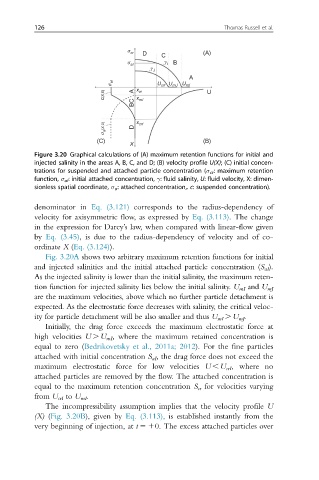
Figure 3.20 Graphical calculations of (A) maximum retention functions for initial and
injected salinity in the areas A, B, C, and D; (B) velocity profile U(X); (C) initial concen-
trations for suspended and attached particle concentration (σ cr : maximum retention
function, σ aI : initial attached concentration, γ: fluid salinity, U: fluid velocity, X: dimen-
sionless spatial coordinate, σ a : attached concentration,. c: suspended concentration).
denominator in Eq. (3.121) corresponds to the radius-dependency of
velocity for axisymmetric flow, as expressed by Eq. (3.113). The change
in the expression for Darcy’s law, when compared with linear-flow given
by Eq. (3.45), is due to the radius-dependency of velocity and of co-
ordinate X (Eq. (3.124)).
Fig. 3.20A shows two arbitrary maximum retention functions for initial
and injected salinities and the initial attached particle concentration (S aI ).
As the injected salinity is lower than the initial salinity, the maximum reten-
tion function for injected salinity lies below the initial salinity. U mI and U mJ
are the maximum velocities, above which no further particle detachment is
expected. As the electrostatic force decreases with salinity, the critical veloc-
ity for particle detachment will be also smaller and thus U mI . U mJ .
Initially, the drag force exceeds the maximum electrostatic force at
high velocities U . U mI , where the maximum retained concentration is
equal to zero (Bedrikovetsky et al., 2011a; 2012). For the fine particles
attached with initial concentration S aI , the drag force does not exceed the
maximum electrostatic force for low velocities U , U crI , where no
attached particles are removed by the flow. The attached concentration is
equal to the maximum retention concentration S cr for velocities varying
from U crI to U mI .
The incompressibility assumption implies that the velocity profile U
(X) (Fig. 3.20B), given by Eq. (3.113), is established instantly from the
very beginning of injection, at t 510. The excess attached particles over