
Page 188 - Formation Damage during Improved Oil Recovery Fundamentals and Applications
P. 188
Formation Damage by Fines Migration: Mathematical and Laboratory Modeling, Field Cases 163
ϕ
f=1
γ =γ J
c =0
c =0
γ J
S a =0
III
S =0
s
x w
II
s =s I x
γ=γ I mI γ I I
c =S aI s =s I x crI
S a =0 γ=γ I s =s I 0
c =c 1
=S γ=γ I
S a a1
c =0 ϕ=–s I (x–x w )
S =S a1
a
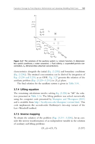
Figure 3.27 The solutions of the auxiliary system (ϕ: stream function, X: dimension-
less spatial coordinate, s: water saturation, γ: fluid salinity, c: suspended particle con-
centration, S a : dimensionless attached concentration).
characteristics alongside the initial (Eq. (3.235)) and boundary conditions
(Eq. (3.236)). The strained concentration can be derived by integration of
Eqs. (3.230 and 3.231) as an ODE. Fig. 3.27 presents the solution of the
auxiliary problem (Eqs. (3.229 3.231))in (X,ϕ) plane.
The final solution for the auxiliary system is given in Table 3.14.
3.7.4 Lifting equation
The remaining calculations involve solving Eq. (3.226) to “lift” the solu-
tion presented in Table 3.14. The lifting problem was solved numerically
using the computer code presented by Shampine and Thompson (2001)
and is available from http://faculty.smu.edu/shampine/current.html. This
code implements the second-order Richtmyer’s two-step variant of the
Lax Wendroff method.
3.7.5 Inverse mapping
To obtain the solution of the problem (Eqs. (3.211 3.220)), let us con-
sider the inverse transformation of an independent variable in the solution
of auxiliary and lifting problems:
ð X; ϕÞ- X; TÞ: (3.237)
ð