
Page 192 - Formation Damage during Improved Oil Recovery Fundamentals and Applications
P. 192
166 Thomas Russell et al.
(A) T
c =0
f =1
III
γ = γ J =0 S s (x,t)
c =0 S s
γ = γ J II
T 2
S a =0 γ = γ I I S (x,t)
s
T
1
S =0 (x,t) γ = γ I γ = γ I S =0
a
c(x,t) c(x,t) S a = S s
X w X mI X crI c =0 0 S a a1 X
(B) S s
T1
T2
(C) S a T1 X
T2
(D) c X
T1
T2
X
(E) γ T1
T2
X
(F) s
T1 T2
X
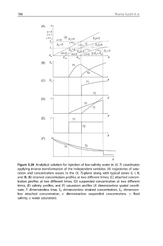
Figure 3.28 Analytical solution for injection of low-salinity water in (X, T) coordinates
applying inverse transformation of the independent variables: (A) trajectories of satu-
ration and concentration waves in the (X, T)-plane along with typical zones 0, I, II,
and III; (B) strained concentration profiles at two different times; (C) attached concen-
tration profiles at two different times; (D) suspended concentration at two different
times, (E) salinity profiles, and (F) saturation profiles (X: dimensionless spatial coordi-
nate, T: dimensionless time, S s : dimensionless strained concentration, S a : dimension-
less attached concentration, c: dimensionless suspended concentration, γ: fluid
salinity, s: water saturation).