
Page 121 - Subyek Teknik Mesin - Forsthoffers Best Practice Handbook for Rotating Machinery by William E Forsthoffer
P. 121
Compressor Best Practices Be st Practice 3.1
Thetypeofcompressorthat willbeusedfor aspecific Positive displacement compressors
application therefore depends on the flow rate and pres-
sure required, and the characteristics of the gas to be Positive displacement compressors are used for low flow and/or
compressed. low molecular weight (hydrogen mixture) applications. The
In general, dynamic compressors are the first preference, various types are presented below.
since they have the lowest maintenance requirements. The
next choice is the rotary type, with positive displacement
compressor since they do not contain valves and are gas Rotary lobe
pulsation-free. The last choice is a reciprocating compressor, A rotary lobe compressor consists of identically synchronized
sincethistype has thehighest maintenancerequirementsand rotors. The rotors are synchronized through use of an external,
produces gas pulsations. However, the type that is finally oil-lubricated, timing gear, which positively prevents rotor
chosen depends upon the specific requirements of the appli- contact, and which minimizes meshing rotor clearance to
cation, as discussed below. optimize efficiency. This feature also allows the compressor to
Figure 3.1.1 presents a flow range chart showing the various be oil free in the gas path. The rotors of the two-lobe compressor
types of compressor applications as a function of flow (acfm) each have two lobes. When the rotor rotates, gas is trapped
and discharge pressure (psig). between the rotor lobes and the compressor casing. The rotating
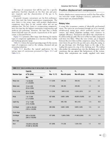
Table 3.1.1 shows the typical operating ranges for the various rotor forces the gas from the gas inlet port, along the casing, to
types of compressors used in the refining, chemical and gas the gas discharge port. Discharge begins as the edge of the
processing industries. leading lobe passes the edge of the discharge port. The trailing
Table 3.1.2 describes the typical applications for the lobe pushes the entrapped gas into the discharge port, which
various types of compressors presented in Figure 3.1.1 and compresses the gas against the backpressure of the system.
Table 3.1.1. Rotary lobe compressors are usually supplied with noise
Table 3.1.1 Typical operating range of various types of gas compressors
Capacity T 2 P 1 P 2
3
Machine Type m /hr (icfm) Max C( F) Max kPa (psia) Max kPa (psia) P/R Min P/R Max
Min Max
Rotary lobe 1 to 68,000 177 (350) 240 (35) 380 (55) 1.0þ 2.4
(1 to 40,000)
Rotary vane 75 to 5,500 177 (350) 340 (45) 450 (65) 1.3 3.2
(45 to 3,300)
Rotary screw 80 to 34,000 177 (350) 1,000 b (150) 4,250 () (615) 2.0 6.0
(50 to 20,000)
Recip 1 to 17,000 427 (800) 6,900 (1,000) 69,000 (10,000) 3.0 50.0
(1 to 10,000)
Liquid ring 17 to 17,000 N/A 690 (100) 965 (140) 1.0þ 10.0
(10 to 10,000)
Centrifugal 1,200 to 250,000 260 (500) 6,900 (1,000) 9,650 (1,400) 1.0þ 3.4
(700 to 150,000)
Single stage
Centrifugal 500 to 250,000 427 (800) 13,800 (2,000) 41,400 (6,000) 2.0 10.0
(300 to 150,000)
Multi stage
Axial 125,000 to 600,000 427 (800) 210 (30) 1,030 (150) 1.0 10.0
(75,000 to 350,000)
95