
Page 123 - Subyek Teknik Mesin - Forsthoffers Best Practice Handbook for Rotating Machinery by William E Forsthoffer
P. 123
Compressor Best Practices Be st Practice 3.1
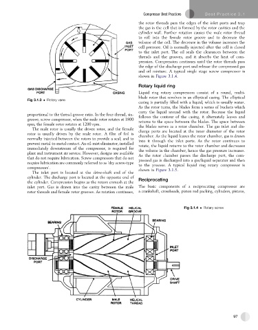
the rotor threads pass the edges of the inlet ports and trap
the gas in the cell that is formed by the rotor cavities and the
cylinder wall. Further rotation causes the male rotor thread
to roll into the female rotor groove and to decrease the
volume of the cell. The decrease in the volume increases the
cell pressure. Oil is normally injected after the cell is closed
to the inlet port. The oil seals the clearances between the
threads and the grooves, and it absorbs the heat of com-
pression. Compression continues until the rotor threads pass
theedgeofthe dischargeport and releasethe compressedgas
and oil mixture. A typical single stage screw compressor is
shown in Figure 3.1.4.
Rotary liquid ring
Liquid ring rotary compressors consist of a round, multi-
blade rotor that revolves in an elliptical casing. The elliptical
Fig 3.1.3 Rotary vane
casing is partially filled with a liquid, which is usually water.
As the rotor turns, the blades form a series of buckets which
carry the liquid around with the rotor. Because the liquid
proportional to the thread-groove ratio. In the four-thread, six- follows the contour of the casing, it alternately leaves and
groove, screw compressor, when the male rotor rotates at 1800 returns to the space between the blades. The space between
rpm, the female rotor rotates at 1200 rpm. thebladesservesas a rotorchamber.The gasinlet anddis-
The male rotor is usually the driven rotor, and the female charge ports are located at the inner diameter of the rotor
rotor is usually driven by the male rotor. A film of foil is chamber. As the liquid leaves the rotor chamber, gas is drawn
normally injected between the rotors to provide a seal, and to into it through the inlet ports. As the rotor continues to
prevent metal-to-metal contact. An oil-mist eliminator, installed rotate, the liquid returns to the rotor chamber and decreases
immediately downstream of the compressor, is required for thevolumeinthe chamber,hencethegaspressureincreases.
plant and instrument air service. However, designs are available As the rotor chamber passes the discharge port, the com-
that do not require lubrication. Screw compressors that do not pressed gas is discharged into a gas/liquid separator and then
require lubrication are commonly referred to as ‘dry screw-type to the process. A typical liquid ring rotary compressor is
compressors’. shown in Figure 3.1.5.
The inlet port is located at the drive-shaft end of the
cylinder. The discharge port is located at the opposite end of Reciprocating
the cylinder. Compression begins as the rotors enmesh at the
inlet port. Gas is drawn into the cavity between the male The basic components of a reciprocating compressor are
rotor threads and female rotor grooves. As rotation continues, a crankshaft, crossheads, piston rod packing, cylinders, pistons,
Fig 3.1.4 Rotary screw
97