
Page 122 - Subyek Teknik Mesin - Forsthoffers Best Practice Handbook for Rotating Machinery by William E Forsthoffer
P. 122
Be st Practice 3 .1 Compressor Best Practices
Table 3.1.2 Typical compressor applications
Compressor Type Application
Rotary lobe Conveying e powder, polyethylene
Rotary vane air Air blowers (low volume). Also used as gas turbine starters
Rotary screw Plant and instrument air, low flow process e off gas, recycle, sulfur blowers
Rotary liquid ring Crude unit vacuum, various saturated gas applications
Reciprocating Plant and instrument air off gas (low flow) recycle (low flow) H 2 make-up, gas reinjection (low flow)
Centrifugal single stage Air blowers, recycle
Centrifugal single stage e integral gear Low flow recycle, off gas, plant air (can replace a recip. in low flow, medium to high molecular weight
applications)
Centrifugal multi-stage side load (horizontal split (Propane, propylene, ethylene, Freon, mixed gas) refrigeration
or barrel)
Centrifugal multi-stage barrel Recycle, reinjection, syn gas
Centrifugal multi-stage e integral gear Plant and instrument air *Process applications require proven field experience
Axial compressor FCC blower, MTBE effluent, gas turbine air
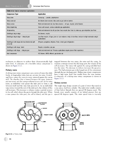
enclosures or silencers to reduce their characteristically high trapped between the two vanes, the rotor and the casing. As
noise level. A schematic of a two-lobe rotary compressor is rotation continues toward the discharge port, the volume of the
shown in Figure 3.1.2. cell decreases. The vanes ride against the casing and slide back
into the rotor. The decrease in volume increases the gas pres-
Rotary vane sure. The high pressure gas is discharged out of the compressor
through the gas discharge port. Sliding-vane rotary compressors
A sliding-vane rotary compressor uses a series of vanes that slide
freely, in longitudinal slots that are cut into the rotor. Centrif- have a high noise level that results from the vane motion.
ugal force causes the vanes to move outward against the casing A schematic of a sliding-vane rotary compressor is shown in
wall. The chamber that is formed between the rotor, between Figure 3.1.3.
any two vanes, and the casing is referred to as a cell. As the rotor
turns, an individual vane passes the inlet port to form a cell Rotary screw
between itself and the vane that precedes it. As an individual The single-stage design consists of a pair of rotors that mesh in
vane rotates toward the end of the inlet port, the volume of this a one-piece, dual-bore cylinder. The male rotor usually consists
cell increases. This increase in volume creates a partial vacuum of four helical threads that are spaced 90 degrees apart. The
in the cell, which draws the gas in through the inlet port. When female rotor usually consists of six helical grooves that are
a vane passes the inlet port, the cell is closed, and the gas is spaced 60 degrees apart. The rotor speed ratio is inversely
Fig 3.1.2 Rotary lobe
96