
Page 243 - Subyek Teknik Mesin - Forsthoffers Best Practice Handbook for Rotating Machinery by William E Forsthoffer
P. 243
Compressor Best Practices Best Practice 3 .27
Table 3.27.1 Pump performance monitoring
Journal bearing (hydrodynamic)
1. Take value at minimum flow (shut off discharge valve)
Parameter Limits
2. Measure:
1. Radial vibration (peak to peak) 2.5 mils (60 microns)
- P 1 - Driver bhp
2. Bearing pad temperature 220°F (108°C)
- Specific gravity 3. Radial shaft position >30° change and/or
- P 2
30% position change
Where: P 1 and P 2 ¼ psig, bhp ¼ brake horsepower. 4. Lube oil supply temperature 140°F (60°C)
5. Lube oil drain temperature 190°F (90°C)
1. Calculate:
. 6 L u b e l i o s i v c o y t i s f f o s p e c 5 0 %
m Kgp ft lb f DPðkPaÞ :102 DP 2:311 7. Lube oil particle size > 25 microns
A. head produced ¼ 8. Lube oil water content below 200 ppm
Kgm lb m S:G: S:G:
m3 Except for gearboxes where greater values are normal from
hd S:G: hd gpm SG unloaded to loaded.
hr
B. pump efficiency (%) ¼
360 kW 3960 bhp
2. Compare to previous value; if > e10% perform maintenance Fig 3.27.7 Condition monitoring parameters and their alarm limits e
journal bearing (hydrodynamic)
Thrust bearings following section will address the techniques used for predictive
maintenance analysis and root cause analysis techniques.
Figures 3.27.8 and 3.27.9 show condition parameters and their Now that the principles of turbo-compressor performance
limits for anti-friction and hydrodynamic thrust bearings.
have been explained and hopefully understood, they can be
implemented to observe internal turbo-compressor condition
Seals changes. Always remember that we want to know the internal,
Figure 3.27.10 presents condition parameters and their limits not the external condition. Figure 3.27.16 presents the outline
for a pump liquid mechanical seal. of a case history that will show the value of performance con-
dition monitoring.
Auxiliary systems
The first plan
Condition monitoring parameters and their alarm limits are
defined in Figures 3.27.11 and 3.27.12 for lube and pump flush I visited a refinery a few years ago to troubleshoot an existing
systems. turbo-compressor problem. While I was on site, another process
Figures 3.27.13, 3.27.14 and 3.27.15 present condition unit, a reformer, was scheduled for a turnaround. Since I was
monitoring parameters and limits for dynamic compressor per- already on site, I was invited to the pre-turnaround meeting and
formance, liquid seals and seal oil systems. One final recom- became involved with turnaround activities.
mendation is presented in Figure 3.27.13. During this meeting I learned that the recycle compressor
was scheduled for a bearing inspection only (radial and thrust). I
asked why. The answer was that it was normal practice. I asked
Predictive maintenance (PDM) techniques if I could see the bearing condition monitoring data (vibration,
bearing displacement, bearing temperature, oil flow e valve
Now that the component condition monitoring parameters and
position and oil sample). I was shown to a room and told “It’sin
their limits have been presented, predictive maintenance tech-
niques must be used if typical condition limits are exceeded. The
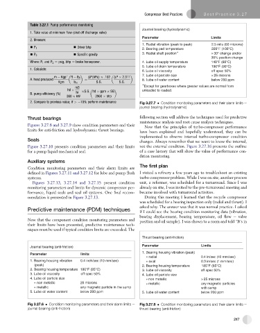
Thrust bearing (anti-friction)
Parameter Limits
Journal bearing (anti-friction)
1. Bearing housing vibration (peak)
Parameter limits
a r l a i d 4 . 0 s / n i e c 1 ( 0 m m s / e ) c
1. Bearing housing vibration 0.4 inch/sec (10 mm/sec) a l a i x 3 . 0 s / n i e c 1 ( m m s / e ) c
(peak) 2. Bearing housing temperature 185°F (85°C)
2. Bearing housing temperature 180°F (85°C) 3. Lube oil viscosity off spec 50%
3. Lube oil viscosity off spec 50% 4. Lube oil particle size
4. Lube oil particle size non metallic > 25 microns
non metallic 25 microns m c i l l a t e a n y m a g n c i t e p e l c i t r a s
metallic any magnetic particle in the sump with sump
5. Lube oil water content below 200 ppm 5. Lube oil water content below 200 ppm
Fig 3.27.6 Condition monitoring parameters and their alarm limits e Fig 3.27.8 Condition monitoring parameters and their alarm limits e
journal bearing (anti-friction) thrust bearing (anti-friction)
217