
Page 241 - Subyek Teknik Mesin - Forsthoffers Best Practice Handbook for Rotating Machinery by William E Forsthoffer
P. 241
Compressor Best Practices Best Practice 3 .27
compressor section. Examine the relationship for polytropic The other available options include compensation for gas
head and you will see that this approach yields a more accurate composition changes, system backups that will protect the
approximation of the operating point. This is because input of T 1 compressor in the event of a surge and controller output and
and T 2 allow calculation of: options to enable the surge system to be soft in relation to the
process system. That is, operation of the surge control system
N 1 and M:W:
N ; T 1 ; Z 1 will not adversely affect the process system.
Best Practice 3.27Practice 3.27Practice 3.27
Best
Best
Trend centrifugal compressor performance (head and ef- traditional mechanical monitoring (vibration, bearing tem-
ficiency) and integrate performance trends with compo- peratures and seal condition) will significantly reduce
nent mechanical condition trends to achieve the highest compressor reliability and revenue.
possible level of safety and reliability. The majority of plants that we visit still define condition monitoring
Use the concept of component condition monitoring to trend the of un-spared compressors by mechanical condition monitoring only.
following components and quickly determine causes of condition As a result, centrifugal compressor disassembly is still done on a time
change: basis (preventive maintenance) and not on a condition basis (predictive
Rotor maintenance).
Journal bearings
Thrust bearings Benchmarks
Shaft end seals This best practice has been used in all sectors of the industry since the
Auxiliary systems mid-1980s to achieve centrifugal compressor reliabilities in excess of
99.7%, and to minimize turnaround activity. Clean compressor ser-
vices (refrigeration) were not dissembled for internal inspection until the
Lessons Learned 4 th 4-year turnaround, based on this best practice (after 16 years of
Approximately 80% of the root causes of component fail- operation).
ure are contained in process changes. Failure to integrate
performance monitoring (head and efficiency) with
B.P. 3.27. Supporting Material Regardless of the type of machinery, monitor these compo-
nents, and you will know the total condition of the machine.
The major machinery components Component condition monitoring
Think of all the machinery that you have been associated with As previously stated, component and system functions must first
and ask; “What are the major components and systems that are be defined and the normal values for each component listed.
common to all types of rotating equipment?” These facts are presented in Figure 3.27.2.
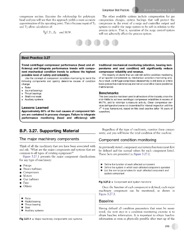
Figure 3.27.1 presents the major component classifications
for any type of machinery:
- Pumps Define the function of each affected component
- Steam turbines Define the system in which each affected component operates
List the normal parameters for each affected component and
- Compressors system component
- Motors
- Gas turbines
- Fans Fig 3.27.2 Component and system functions
- Others Once the function of each component is defined, each major
machinery component can be monitored, as shown in
Figure 3.27.3.
Rotor
Radial bearing Baseline
Thrust bearing
Seal Having defined all condition parameters that must be moni-
Auxiliary systems
tored, the next step in a condition monitoring exercise is to
obtain baseline information. It is important to obtain baseline
Fig 3.27.1 Major machinery components and systems information as soon as physically possible after start-up of the
215