
Page 244 - Subyek Teknik Mesin - Forsthoffers Best Practice Handbook for Rotating Machinery by William E Forsthoffer
P. 244
Be st Practice 3 .27 Compressor Best Practices
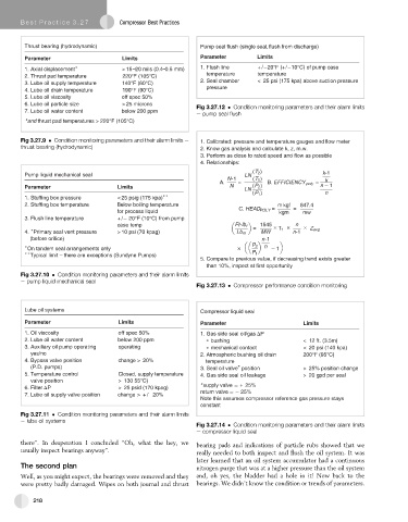
Thrust bearing (hydrodynamic) Pump seal flush (single seal,flush from discharge)
Parameter Limits Parameter Limits
1. Axial displacement > 15–20 mils (0.4–0.5 mm) 1. Flush line +/ 20°F(+/ 10°C) of pump case
temperature temperature
2. Thrust pad temperature 220°F (105°C)
3. Lube oil supply temperature 140°F (60°C) 2. Seal chamber < 25 psi (175 kpa) above suction pressure
pressure
4. Lube oil drain temperature 190°F (90°C)
5. Lube oil viscosity off spec 50%
6. Lube oil particle size > 25 microns Fig 3.27.12 Condition monitoring parameters and their alarm limits
7. Lube oil water content below 200 ppm
e pump seal flush
and thrust pad temperatures > 220°F (105°C)
Fig 3.27.9 Condition monitoring parameters and their alarm limits e 1. Calibrated: pressure and temperature gauges and flow meter
thrust bearing (hydrodynamic) 2. Know gas analysis and calculate k, z, m.w.
3. Perform as close to rated speed and flow as possible
4. Relationships:
(T 2 ) k-1
Pump liquid mechanical seal LN
N-1 (T 1 )
A. = B. EFFICIENCY poly = k
Parameter Limits N LN (P 2 ) n 1
(P 1 ) n
1. Stuffing box pressure < 25 psig (175 kpa)
2. Stuffing box temperature Below boiling temperature m kgf 847.4
C. HEAD POLY = =
for process liquid kgm mw
3. Flush line temperature + / 20°F (10°C) from pump
case temp Ft-lb f 1545 × × n ×
4. Primary seal vent pressure > 10 psi (70 kpag) Lb m = MW T 1 n-1 Z avg
(before orifice) n-1
On tandem seal arrangements only × P 2 n 1
Typical limit – there are exceptions (Sundyne Pumps) P 1
5. Compare to previous value, if decreasing trend exists greater
than 10%, inspect at first opportunity
Fig 3.27.10 Condition monitoring parameters and their alarm limits
e pump liquid mechanical seal
Fig 3.27.13 Compressor performance condition monitoring
Lube oil systems Compressor liquid seal
Parameter Limits Parameter Limits
. 1 l i O s i v c o y t i s f f o s p e c 5 0 % 1. Gas side seal oil/gas P
2. Lube oil water content below 200 ppm bushing < 12 ft. (3.5m)
3. Auxiliary oil pump operating operating mechanical contact < 20 psi (140 kpa)
yes/no 2. Atmospheric bushing oil drain 200°F (95°C)
4. Bypass valve position change > 20% temperature
(P.D. pumps) 3. Seal oil valve position > 25% position change
5. Temperature control Closed, supply temperature 4. Gas side seal oil leakage > 20 gpd per seal
valve position > 130 55°C)
supply valve + 25%
6. Filter P > 25 psid (170 kpag)
7. Lube oil supply valve position change > + / 20% return valve 25%
Note this assumes compressor reference gas pressure stays
constant
Fig 3.27.11 Condition monitoring parameters and their alarm limits
e lube oil systems
Fig 3.27.14 Condition monitoring parameters and their alarm limits
e compressor liquid seal
there”. In desperation I concluded “Oh, what the hey, we bearing pads and indications of particle rubs showed that we
usually inspect bearings anyway”. really needed to both inspect and flush the oil system. It was
later learned that an oil system accumulator had a continuous
The second plan nitrogen purge that was at a higher pressure than the oil system
Well, as you might expect, the bearings were removed and they and, oh yes, the bladder had a hole in it! Now back to the
were pretty badly damaged. Wipes on both journal and thrust bearings. We didn’t know the condition or trends of parameters.
218