
Page 245 - Subyek Teknik Mesin - Forsthoffers Best Practice Handbook for Rotating Machinery by William E Forsthoffer
P. 245
Compressor Best Practices Best Practice 3 .27
- When we finally got the compressor apart e two days after
Compressor liquid seal oil systems the turnaround was complete, we got lucky e the internals
including the balance drum were perfect!
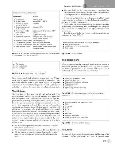
Parameters Limits
If only we had established a performance condition moni-
1. Oil viscosity off spec 50%
toring program, as well as seal, bearing, balance drum and lube/
2. Oil flash point below 200°F (100°C) seal system condition monitoring.
3. Auxiliary oil pump operating
operating yes/no Incidentally, this was a major refinery that placed high value
on reliability, maintainability, root cause analysis, etc. They had
4. Bypass valve position change > 20%
(P.D. pumps) all the books and had sent people to the right workshops e even
5. Temperature control closed, supply temperature 130°F one of mine!
valve position (55°C) The objectives of turbo-compressor condition monitoring are
6. Filter P 25 psid (170 kpag) presented in Figure 3.27.17.
7. Seal oil valve position change > 20% open (supply)
> 20% closed (return)
8. Seal oil drainer condition (proper operation)
9. Constant level (yes/no) level should be observed Know turbo-compressor internal condition to determine:
10. Observed level (yes/no) level should not be constant Loss of daily revenue
11. Time between drains approximately 1 hour (depends on Justification for turnaround activities
drainer volume) Root cause
Fig 3.27.15 Condition monitoring parameters and their alarm limits Fig 3.27.17 The objectives
e compressor liquid seal oil systems
The parameters
The first plan What parameters must be measured? Readers should be able to
The second plan answer this question readily at this point. Fig 3.27.18 presents
The third plan
the reduced parameters e the answers and Figure 3.27.19
contains all the factors necessary for calculation.
Fig 3.27.16 ‘The long, long, long, turnaround’
Were there upsets? High vibrations, temperatures, etc.? Were Polytropic (or isentropic) head
there a lot of surges? Nobody could seem to remember! Does Actual inlet flow rate
this sound familiar? Well, as you might expect, we prepared Polytropic (or isentropic) efficiency
a second plan e we had better inspect the oil seals. After all, we Polytropic exponent
didn’t have to get into the compressor so we had sufficient time. Horsepower
Speed (or guide vane position)
The third plan
Fig 3.27.18 The turbo-compressor performance condition
No doubt about it, the seals were really bad. Bushing seals, both parameters
the atmospheric bushings and gas side bushings were wiped and
the atmospheric side showed typical evidence of high DT,
probably due to start-up on low pressure N 2 (to save N 2 costs).
Since the gas was sweet, seal leakage was returned to the res- From gas analysis and equation of state
ervoir via a degassing tank and there was no seal condition M.W.
K average
monitoring trend data available. (Seal oil leakage e gas side, seal Z inlet
oil leakage e atmospheric side, which could have been obtained
P 1 ,P 2
by trending seal oil valve position). Am I making my point? Well, T 1 ,T 2
it was crunch time (decision time). Were the damaged seals the Flow rate
root cause of bearing failure? Was it the dirty lube and seal Speed (if applicable)
system or was there another deeper cause inside of the com- Guide vane position (if applicable)
pressor? I could go on and on but in the interest of time let it
suffice to say:
Fig 3.27.19 The data (factors) required
- We decided to open the barrel and compressor e we had
time, based on schedule.
- We could not find tools and when we did, they did not work. Accuracy
- Oh yes, a piece of a suction strainer (supposedly only for
start-up) had been lodged in the case/barrel interface for Accuracy of data involves both calibration and location of in-
years. struments. Before proceeding, we need to present some
219