
Page 319 - Subyek Teknik Mesin - Forsthoffers Best Practice Handbook for Rotating Machinery by William E Forsthoffer
P. 319
Steam Turbine Best Practices Best Practice 5 .11
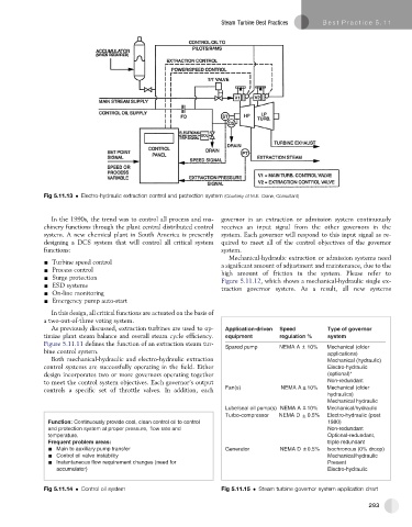
Fig 5.11.13 Electro-hydraulic extraction control and protection system (Courtesy of M.E. Crane, Consultant)
In the 1990s, the trend was to control all process and ma- governor in an extraction or admission system continuously
chinery functions through the plant central distributed control receives an input signal from the other governors in the
system. A new chemical plant in South America is presently system. Each governor will respond to this input signal as re-
designing a DCS system that will control all critical system quired to meet all of the control objectives of the governor
functions: system.
Mechanical-hydraulic extraction or admission systems need
- Turbine speed control a significant amount of adjustment and maintenance, due to the
- Process control high amount of friction in the system. Please refer to
- Surge protection Figure 5.11.12, which shows a mechanical-hydraulic single ex-
- ESD systems traction governor system. As a result, all new systems
- On-line monitoring
- Emergency pump auto-start
In this design, all critical functions are actuated on the basis of
a two-out-of-three voting system.
As previously discussed, extraction turbines are used to op- Application-driven Speed Type of governor
timize plant steam balance and overall steam cycle efficiency. equipment regulation % system
Figure 5.11.11 defines the function of an extraction steam tur- Spared pump NEMA A + 10% Mechanical (older
bine control system. – applications)
Both mechanical-hydraulic and electro-hydraulic extraction Mechanical (hydraulic)
control systems are successfully operating in the field. Either Electro-hydraulic
design incorporates two or more governors operating together (optional)*
to meet the control system objectives. Each governor’s output Non-redundant
–
controls a specific set of throttle valves. In addition, each Fan(s) NEMA A + 10% Mechanical (older
hydraulics)
Mechanical hydraulic
Lube/seal oil pump(s) NEMA A + 10% Mechanical/hydraulic
–
Turbo-compressor NEMA D + – 0.5% Electro-hydraulic (post
Function: Continuously provide cool, clean control oil to control 1980)
and protection system at proper pressure, flow rate and Non-redundant
temperature. Optional-redundant,
Frequent problem areas: triple redundant
Main to auxiliary pump transfer Generator NEMA D + – 0.5% Isochronous (0% droop)
Control oil valve instability Mechanical/hydraulic
Instantaneous flow requirement changes (need for Present
accumulator) Electro-hydraulic
Fig 5.11.14 Control oil system Fig 5.11.15 Steam turbine governor system application chart
293