
Page 315 - Subyek Teknik Mesin - Forsthoffers Best Practice Handbook for Rotating Machinery by William E Forsthoffer
P. 315
Be st Practice 5 .11 Steam Turbine Best Practices
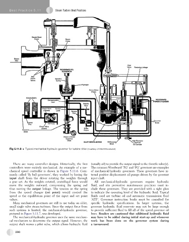
Fig 5.11.8 Typical mechanical-hydraulic governor for turbine drive (Courtesy of Elliott/Woodward)
There are many controller designs. Historically, the first (usually oil) to provide the output signal to the throttle valve(s).
controllers were entirely mechanical. An example of a me- The common Woodward ‘TG’ and ‘PG’ governors are examples
chanical speed controller is shown in Figure 5.11.6.Com- of mechanical/hydraulic governors. These governors have in-
monly called ‘flyball governors’, they worked by having the ternal positive displacement oil pumps driven by the governor
input shaft from the driver rotating the weights through input shaft.
a gear set. As the weights rotated, centrifugal force would All mechanical-hydraulic governors require hydraulic
move the weights outward, compressing the spring and fluid, and site preventive maintenance practices must in-
thus moving the output linkage. The tension on the spring clude these governors. They are provided with a sight glass
from the speed changer (set point) would control the to indicate the operating level of the hydraulic fluid. Typical
speed as the equilibrium point of the input and set point fluids used are turbine oil and automatic transmission fluid
values. ‘ATF’. Governor instruction books must be consulted for
Many mechanical governors are still in use today on older, specifichydraulic specifications. In larger systems, the
small single valve steam turbines. Since the output force from governor hydraulic fluid reservoir may not be large enough
such systems is limited, the mechanical-hydraulic governor, to provide sufficient fluid to fill all of the speed governor oil
pictured in Figure 5.11.7, was developed. lines. Readers are cautioned that additional hydraulic fluid
The mechanical-hydraulic governor uses the same mechani- may have to be added during initial start-up and whenever
cal mechanism to determine the output signal. However, the work has been done on the governor system during
output shaft moves a pilot valve, which allows hydraulic fluid a turnaround.
290