
Page 316 - Subyek Teknik Mesin - Forsthoffers Best Practice Handbook for Rotating Machinery by William E Forsthoffer
P. 316
Steam Turbine Best Practices Best Practice 5 .11
Figure 5.11.9 presents the important facts concerning this
system.
Do not require a mechanical input signal
Provide extremely accurate control Since they did not require a mechanical (gear or shaft drive)
Provide self diagnostics, fault tolerance and auto-start input signal, these governors could be exchanged while the op-
capability erators kept the turbine in the manual mode. As an analogy,
Require actuator to convert electric output signal to control exchanging automatic control valves is the same procedure. In
signal (hydraulic or pneumatic) this case, the operator maintains process conditions by manually
Types: throttling the bypass valve while the automatic control valve
Analog
Digital undergoes repair.
Either type can be: The first electronic governors were analog, and needed sig-
Non-redundant nificant maintenance to change out cards. Digital governors were
Redundant introduced in the late 1970s, and are the only type of speed
Triple redundant
control used today. As micro-processors became popular, digital
governors also offered the great advantage of redundancy. Re-
dundant and triple redundant governors became very popular,
Fig 5.11.9 Electro-hydraulic governors
because they could now automatically transfer on-line to allow
control to be maintained while the other governor required
Figure 5.11.8 is a representation of a mechanical-hydraulic maintenance. Operator assistance was no longer required.
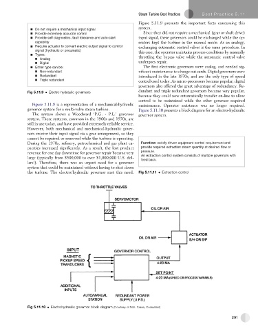
governor system for a multi-valve steam turbine. Figure 5.11.10 presents a block diagram for an electro-hydraulic
The system shows a Woodward ‘P.G. - P.L.’ governor governor system.
system. These systems, common in the 1960s and 1970s, are
still in use today, and have provided extremely reliable service.
However, both mechanical and mechanical-hydraulic gover-
nors receive their input signal via a gear arrangement, so they
cannot be repaired or removed while the turbine is operating.
During the 1970s, refinery, petrochemical and gas plant ca- Function: satisfy driven equipment control requirement and
pacities increased significantly. As a result, the lost product provide required extraction steam quantity at desired flow or
revenue for one day downtime for governor repair became very pressure.
An extraction control system consists of multiple governors with
large (typically from $500,000 to over $1,000,000 U.S. dol- feed back.
lars!). Therefore, there was an urgent need for a governor
system that could be maintained without having to shut down
the turbine. The electro/hydraulic governor met this need. Fig 5.11.11 Extraction control
Fig 5.11.10 Electrohydraulic governor block diagram (Courtesy of M.E. Crane, Consultant)
291