
Page 312 - Subyek Teknik Mesin - Forsthoffers Best Practice Handbook for Rotating Machinery by William E Forsthoffer
P. 312
Steam Turbine Best Practices Best Practice 5 .11
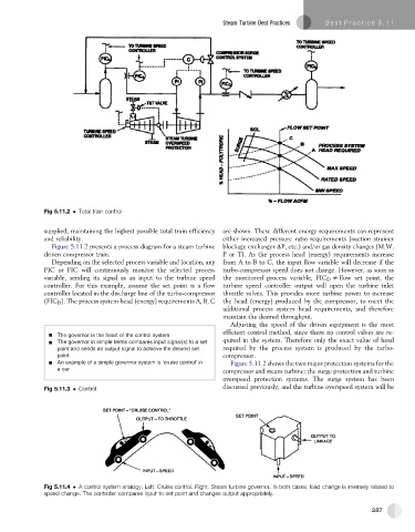
Fig 5.11.2 Total train control
supplied, maintaining the highest possible total train efficiency are shown. These different energy requirements can represent
and reliability. either increased pressure ratio requirements (suction strainer
Figure 5.11.2 presents a process diagram for a steam turbine blockage exchanger DP, etc.) and/or gas density changes (M.W.
driven compressor train. P or T). As the process head (energy) requirements increase
Depending on the selected process variable and location, any from A to B to C, the input flow variable will decrease if the
PIC or FIC will continuously monitor the selected process turbo-compressor speed does not change. However, as soon as
variable, sending its signal as an input to the turbine speed the monitored process variable, FIC D s flow set point, the
controller. For this example, assume the set point is a flow turbine speed controller output will open the turbine inlet
controller located in the discharge line of the turbo-compressor throttle valves. This provides more turbine power to increase
(FIC D ). The process system head (energy) requirements A, B, C the head (energy) produced by the compressor, to meet the
additional process system head requirements, and therefore
maintain the desired throughput.
Adjusting the speed of the driven equipment is the most
efficient control method, since there no control valves are re-
The governor is the heart of the control system
quired in the system. Therefore only the exact value of head
The governor in simple terms compares input signal(s) to a set
point and sends an output signal to achieve the desired set required by the process system is produced by the turbo-
point. compressor.
An example of a simple governor system is ‘cruise control’ in Figure 5.11.2 shows the two major protection systems for the
a car
compressor and steam turbine: the surge protection and turbine
overspeed protection systems. The surge system has been
Fig 5.11.3 Control discussed previously, and the turbine overspeed system will be
Fig 5.11.4 A control system analogy. Left: Cruise control. Right: Steam turbine governor. In both cases, load change is inversely related to
speed change. The controller compares input to set point and changes output appropriately.
287