
Page 311 - Subyek Teknik Mesin - Forsthoffers Best Practice Handbook for Rotating Machinery by William E Forsthoffer
P. 311
Be st Practice 5 .11 Steam Turbine Best Practices
, Review test set-up drawing , Obtain documents for data reduction check e if
, Review data calculation (data reduction) methods applicable (flow meter equations, gas data, etc.)
, Define work scopes for site personnel (assembly and - During test
disassembly witness, video or still frame pictures, etc.) Note: coordinate with test personnel to avoid
, Confirm assigned vendor service engineers will be in interference
attendance for: , Review ‘as measured’ raw data for consistency
, Assembly , ‘Walk’ equipment e look for leaks, contract
, Disassembly instrument, piping and baseplate vibration, etc.
, Test , Use test team effectively e assign a station to each
individual
, Ask all questions now, not later, while an opportunity
Shop test activity
exists to correct the problem
- Review and understand test agenda prior to test , Check vendor's data reduction for rated point e if
- Immediately prior to test meet with assigned test applicable
engineer to: - After test
, Review schedule of events , Inspect all components as required by the test agenda
, Designate a team leader (bearings, seals, labyrinths, RTD wires, etc.)
, Confirm test team leader will be notified prior to each , Review data reduction of performance data corrected
event to guarantee conditions
, ‘Walk’ test set-up to identify each instrumented , Review e all mechanical test data
point , Generate list of action (if applicable) prior to
, Confirm calibration of each test instrument acceptance of test
, Approve or reject
Best
Best
Best Practice 5.11Practice 5.11Practice 5.11
Perform coupled overspeed trip checks for turbines with failure of turbine overspeed trip devices during the
electronic governors and overspeed trip systems. uncoupled overspeed trip checks.
Checking overspeed trip systems with turbines uncoupled exposes
personnel and nearby assets to safety issues, since steam energy Benchmarks
compared to the uncoupled power requirement can accelerate the This best practice has been recommended to clients since 2005, when
turbine to speeds which exceed the rotor maximum design stress. insurance companies accepted it for turbines with electronic governors
Electronic governor systems allow the overspeed trip setting to be over uncoupled overspeed trip checks. Note: Since the electronic
reduced, which permits confirmation of trip system function without governor is supplied with overspeed detection trip capability, the
exposing personnel to dangerous consequences. mechanical trip bolts can be disabled and removed if an additional
independent electrical trip system is used (“Protech”, “Turbosentry” or
Lessons Learned equivalent).
Machinery historical case studies are full of examples of
failed turbines and personnel injury resulting from the
Meet driven equipment control requirements
Compressor – pressure or flow
Pump – pressure, flow or level
B.P. 5.11. Supporting Material Generator – load
Meet above objectives when in series or parallel with other
trains
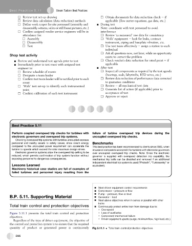
Total train control and protection objectives Continuously protect entire train from damage due to:
Overspeed
Figure 5.11.1 presents the total train control and protection Loss of auxiliaries
objectives. Component mechanical failure
Driven equipment upsets (surge, minimum flow, high load, etc.)
Regardless of the type of driven equipment, the objective of
the control and protection system is to ensure that the required
quantity of product or generated power is continuously Fig 5.11.1 Total train control/protection objectives
286