
Page 320 - Subyek Teknik Mesin - Forsthoffers Best Practice Handbook for Rotating Machinery by William E Forsthoffer
P. 320
Be st Practice 5 .11 Steam Turbine Best Practices
Usually, the hydraulic control system is integral with the
The protection system monitors steam turbine total train lubrication system. Typical pressure operating ranges for these
parameters and ensures safety and reliability by the following systems are:
action:
Start-up (optional) provides a safe, reliable fully automatic start- Low pressure: 276e690 kPa (40e100 PSI)
up and will shut down the turbine on any abnormality Medium pressure: 827e4,137 kPa (120e600 PSI)
Manual shutdown High pressure Above: 4,137 kPa (600 PSI)
Trip valve exerciser allows trip valve stem movement to be
confirmed during operation without shutdown Figure 5.11.15 is an application chart showing type of gov-
Rotor overspeed monitors turbine rotor speed and will shut ernor classification, speed regulation and type of governor used.
down turbine when maximum allowable speed (trip speed) is In general, NEMA A governors are used in general purpose
attained (spared) applications and NEMA D governors are used in special
Excessive process variable signal monitors all train process purpose (un-spared) applications.
variables and will shut down turbine when maximum value is
exceeded
Protection
Fig 5.11.16 Protection The function of the steam turbine protection system is often
confused with the control system, but in fact the two systems
incorporate electro-hydraulic governor arrangements as shown are entirely separate. The protection system operates only when
in Figure 5.11.13. any of the control system set point parameters are exceeded,
Coupled with redundant features, these systems offer and the steam turbine will be damaged if it continues to operate.
high reliability and efficient process control. Regardless of Figure 5.11.16 defines the typical protection methods.
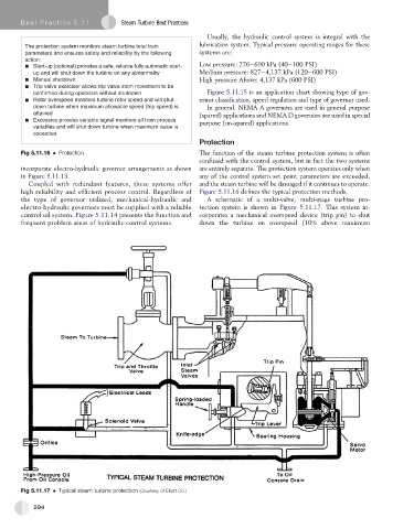
the type of governor utilized, mechanical-hydraulic and A schematic of a multi-valve, multi-stage turbine pro-
electro-hydraulic governors must be supplied with a reliable tection system is shown in Figure 5.11.17.Thissystemin-
control oil system. Figure 5.11.14 presents the function and corporates a mechanical overspeed device (trip pin) to shut
frequent problem areas of hydraulic control systems. down the turbine on overspeed (10% above maximum
Fig 5.11.17 Typical steam turbine protection (Courtesy of Elliott Co.)
294