
Page 370 - Subyek Teknik Mesin - Forsthoffers Best Practice Handbook for Rotating Machinery by William E Forsthoffer
P. 370
Gas Turbine Best Practices Be st Practice 6.8
Best
Best
Best Practice 6.8Practice 6.8Practice 6.8
Require a stainless steel oil reservoir and oil piping for needed extended oil flush times during commissioning,
optimum turbine unit reliability. and have experienced bearing failures which have resulted
Using a stainless steel oil system will minimize start-up oil flushing in unscheduled shutdown (usually one week).
time and ensure a clean, iron-sulfide free oil supply to the turbine for its
whole working life. Benchmarks
Most gas turbine vendors currently (2010) offer stainless steel oil This best practice has been used for all gas turbine oil systems since
reservoirs and piping as an option. the late 1980s, resulting in minimum oil flushing times and zero bearing
Justify the additional cost during the pre-FEED phase of the project
failures due to iron sulfide oil contamination.
by the additional time for oil flushing (chemical treating) a carbon steel
system, and supply case histories describing unscheduled downtimes
and maintenance for carbon steel systems.
Lessons Learned
Industrial case histories are full of incidents involving gas
turbines that have used carbon steel systems. These have
B.P. 6.8. Supporting Material
Lube and hydraulic systems use gravity drain methods for returning lube oil to the reservoir.
Details concerning aero-derivative gas turbine lube systems are
The lubrication and hydraulic systems continuously provide presented in Figure 6.8.1.
clean, cool lubrication and hydraulic fluid to the components at Figure 6.8.2 contains the function definition of the lube and
the proper pressure, temperature and flow. The lubrication hydraulic (control) system and differences between aero-
system used for aero-derivative type gas turbines is different derivative and industrial systems.
from that in an industrial gas turbine, in that a scavenge
(vacuum) system is added in the latter, to return lube oil to the
sump under flight conditions. This system is retained on me-
chanical drive applications of gas turbines. Industrial gas turbines
Function: identical to steam turbine/turbo-compressor –
continuously provide cool, clean oil to bearings and control
components at the proper pressure, temperature and flow rate.
However, due to the high temperatures experienced in gas
turbines and engine design features, there are differences.
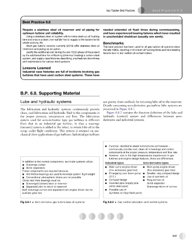
In addition to the normal components, aero-lube systems utilize: Industrial types Aero-derivative types
Scavenge pumps
Main pump engine driven Main pump engine driven
Air/oil separators
(thru accessory gear box) (thru accessory gear box)
These components are required because:
Anti-friction bearings are used to minimize system flight weight Emergency cool down pump Smaller, very compact design
Conventional atmospheric drains are not possible (D.C.) Use of synthetic oil
Oil/air mist from bearings must be: Compact design Requirement of:
Scavenged (drawn) back to reservoir Guarded pipe (supply pipe Air/oil separator
Separated prior to return to reservoir within drain pipe) Scavenge return oil pumps
Both scavenge pumps and separators are engine driven via the Possible use of:
auxiliary gear box Synthetic oil (high flash point)
Fig 6.8.1 Aero-derivative gas turbine lube oil systems Fig 6.8.2 Gas turbine lubrication and control systems
341