
Page 377 - Subyek Teknik Mesin - Forsthoffers Best Practice Handbook for Rotating Machinery by William E Forsthoffer
P. 377
Be st Practice 7 .1 Lube, Seal and Control Oil System Best Practices
Best Practice 7.1
Specify all ambient conditions and desired oil type on the Lessons Learned
oil system data sheet to ensure proper component Different ambient conditions and oil grades than specified
selection. on the data sheet and used in component selection will
Specifying the incorrect ambient temperature limits will affect oil affect the reliability of the oil system and impact the ma-
viscosity and therefore can impact the following components: chinery serviced by the system.
Reservoir heater sizing (lower than specified temperature) Case histories are full of incidents where oil systems that are not
Rotary pump wear (low viscosity e higher than specified designed for the actual ambient conditions, or the oil type in use, have
temperature) caused unscheduled shutdowns and loss of large amounts of
Driver power overload (high viscosity e lower than specified revenue.
temperature)
Cooler heat load (higher than specified temperature) Benchmarks
Filter pressure drop (lower than specified temperature)
This best practice has been used since the mid-1970s, when an oil
The use of a different viscosity grade oil than specified on the data system design audit approach was formulated that has since been
sheet will also affect all of the components mentioned above in the used for all new oil systems and ‘bad actor’ oil systems that had
manner noted. caused more than one shutdown per year. The use of this best practice
has saved countless field shutdowns and maximized process unit
revenue.
B.P. 7.1. Supporting Material Site conditions
This information is required for the proper design of the system
Critical equipment vendor data and should be accurately stated. As a minimum, the data noted
in Figure 7.1.2 should be included. Frequently, this information
This data must be furnished by each critical equipment vendor, is not known until well into the project (if at all), and leads to
and must contain information as shown in Figure 7.1.1.Itis cost adders, delivery delays and unreliable systems. End user
important to note that different vendors furnish different pieces input in the pre-purchase order phase of the project will elim-
of critical equipment in the same unit. In this case, all vendors inate these problems. In addition, determination of auxiliary
should agree to a common lube oil type and common value of oil system arrangements and module location at this time will
supply conditions, if possible. Failure to do so only complicates usually result in simpler, more practical designs that can increase
system design, and requires additional components which can system reliability. A typical auxiliary system vendor data sheet is
reduce system reliability.
included at the end of this chapter. It has been completed to
include both equipment vendor site data and end user required
data for the present example.
Site environmental conditions
All utility data
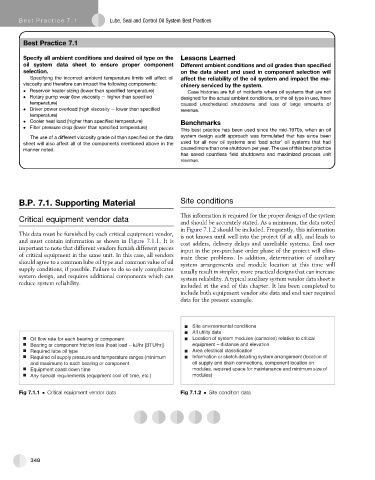
Oil flow rate for each bearing or component Location of system modules (consoles) relative to critical
Bearing or component friction loss (heat load – kJ/hr [BTU/hr]) equipment – distance and elevation
Required lube oil type Area electrical classification
Required oil supply pressure and temperature ranges (minimum Information or sketch detailing system arrangement (location of
and maximum) to each bearing or component oil supply and drain connections, component location on
Equipment coast down time modules, required space for maintenance and minimum size of
Any special requirements (equipment cool off time, etc.) modules)
Fig 7.1.1 Critical equipment vendor data Fig 7.1.2 Site condition data
348