
Page 382 - Subyek Teknik Mesin - Forsthoffers Best Practice Handbook for Rotating Machinery by William E Forsthoffer
P. 382
Lube, Seal and Control Oil System Best Practices Be st Practice 7.5
the amount the components will actually pass, the excess oil will Pump and driver sizing
be bypassed back to the oil reservoir and could create over- Pump performance
heating problems in the system. Conversely, if too low a value of
Regardless of the types of pumps used, centrifugal or positive
component oil flow is specified, a system may continuously
operate with both main and stand-by pump in operation since displacement, the performance curves should be reviewed at
the capacity of the main pump will have been sized too small for this point.
A. Positive displacement e Positive displacement pumps,
the system.
furnished without external timing gears, are mechanically sen-
sitive to fluid viscosity. The performance curve should be
Reservoir sizing, construction, and checked at all operating points to confirm that adequate rotor
sub-component details separation is present at low fluid viscosities. If an operating point
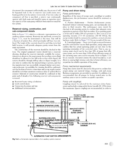
Refer to Figure 7.5.1, which is a schematic representation of an is at the end of within 20% of a pressure vs. flow curve at a low
auxiliary system reservoir. Reservoir size and levels, as noted in operating viscosity (7.4e10 centistokes [50e60 SSU]), the
Figure 7.5.1, must be determined at this time. Size will be pump vendor should be contacted to confirm a correct selection
a function of system flow, which previously will have been de- has been made. Refer to Figure 7.5.2 for an example of this case.
fined. The height of the reservoir should be such that, in its final B. Centrifugal pumps e Since centrifugal pump performance
field location, it will provide adequate gravity return from the must be corrected for viscous fluid operation, pump sizing must
main equipment. confirm that the actual operating points are not close to the
operating extremities of the corrected curve. That is, any op-
The construction of the reservoir should be checked at this
time. The original equipment vendor should have a reservoir erating point should not be less than 20% of pump best effi-
ciency point, nor be more than 110% of best efficiency point of
drawing, detailing the reservoir internals, available for review.
Attention is drawn to the requirement that auxiliary return fluid the operating curve corrected for viscosity. Refer to Figure 7.5.3
should not be allowed to free fall to the surface of the liquid. All for an example. Operation outside the stated boundaries, in ad-
returns should be through stilling tubes or sloped troughs. It is dition to causing high revenue costs due to lower efficiency, can
also wise to confirm that the internal design is proven, and that jeopardize the reliable operation of the pump.
the manufacturer has successfully designed similar such reser-
voirs in the past. Accessibility for cleaning should be confirmed, Pump mechanical requirements
and the location of return connections and pump supply nozzles Pump data sheets must be checked at this point to confirm that
should be such that maximum residence time of system fluid is proper pump case material design, bearings, seals and pump
ensured. Material of construction should be confirmed at this flushing arrangements are provided as specified. In addition, it is
point and all details of the following reservoir sub-components recommended that all pumps be factory tested prior to the
reviewed: auxiliary system test to confirm acceptable operation.
- Reservoir heater sizing calculations Pump unit couplings
- Level control alarm Couplings should be selected for the maximum driver horse-
- Connection locations and size power and include a sizing safety factor (usually 20e25%) above
- Additional instrumentation this maximum. Spacer couplings are recommended, in order to
Fig 7.5.1 Schematic representation of an auxiliary system reservoir
353