
Page 385 - Subyek Teknik Mesin - Forsthoffers Best Practice Handbook for Rotating Machinery by William E Forsthoffer
P. 385
Be st Practice 7 .5 Lube, Seal and Control Oil System Best Practices
i.e. values approaching 220 centistokes (1,000 SSU) e on the
1
order of 1 / 2 to 2 times the selected valve coefficient without
viscosity considerations.
Control valve sensing line snubber devices
(dampers)
If these devices are included, a review of device design and
confirmation of proper installation should be confirmed. Such
devices provide unrestricted flow in one direction and restricted
flow in another. The total auxiliary system operation must
be reviewed in this light to confirm proper installation and
orientation.
Supply pipe velocity checks
The pump header, interconnecting console pipe, and piping
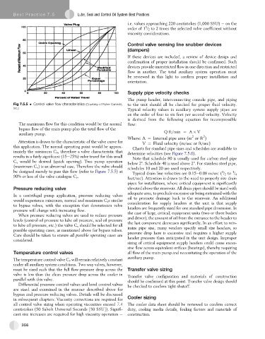
Fig 7.5.5 Control valve flow characteristics (Courtesy of Fisher Controls, to the unit should all be checked for proper fluid velocity.
Inc.)
Typical velocity values in auxiliary system supply pipes are
on the order of four to six feet per second velocity. Velocity
is derived from the following equation for incompressible
The maximum flow for this condition would be the normal flow:
bypass flow of the main pump plus the total flow of the
auxiliary pump. Qft=min ¼ A V
2
2
Where: A ¼ Internal pipe area (m or ft )
Attention is drawn to the characteristic of the valve curve for V ¼ Fluid velocity (m/sec or ft/sec)
this application. The normal operating point would be approx- Charts for standard pipe sizes and schedules are available to
imately the minimum C v , therefore a valve characteristic that determine velocities (see Figure 7.5.6).
results in a fairly significant (15e25%) valve travel for this small Note that schedule 80 is usually used for carbon steel pipe
C v would be desired (quick opening). Two pump operation below 2". Schedule 40 is used above 2". For stainless steel pipe,
(maximum C v ) is an abnormal case. Therefore the valve should schedules 10 and 20 are used respectively.
be designed merely to pass this flow (refer to Figure 7.5.5)at 1 1
Typical drain line velocities are 0.15e0.08 m/sec ( / 2 to / 4
90% or less of the valve catalogue C v .
feet/sec). Attention is drawn to the need to properly size drain
pipes for installations, where critical equipment is significantly
Pressure reducing valve elevated above the reservoir. All drain pipes should be sized with
adequate area, to preclude excessive air being entrained with the
In a centrifugal pump application, pressure reducing valves
would experience minimum, normal and maximum C v s similar oil to promote drainage back to the reservoir. An additional
consideration for supply headers at the unit is that supply
to bypass valves, with the exception that downstream valve
pressure will change with increasing flow. headers are frequently sized for one standard pipe dimension. In
the case of large, critical, equipment units (two or three bodies
When pressure reducing valves are used to reduce pressure
levels (control oil pressure to lube oil pressure, seal oil pressure and driver), the amount of oil from the entrance to the header to
the last component decreases significantly. In an effort to min-
to lube oil pressure, etc.) the valve C v should be selected for all
possible operating cases, as mentioned above for bypass valves. imize pipe size, many vendors specify small size headers, so
pressure drop here is excessive and requires a higher supply
Care should be taken to ensure all possible operating cases are
considered. header pressure than anticipated in the unit design. Improper
sizing of critical equipment supply headers could cause exces-
sive flow across equivalent orifices (bearings), thereby requiring
Temperature control valves all flow of the main pump and necessitating the operation of the
auxiliary pump.
The temperature control valve C v will remain relatively constant
under all auxiliary system conditions. Two way valves, however,
must be sized such that the full flow pressure drop across the Transfer valve sizing
valve is less than the clean pressure drop across the cooler in
Transfer valve configuration and materials of construction
parallel with this valve. should be confirmed at this point. Transfer valve design should
Differential pressure control valves and level control valves be checked to confirm tight shutoff.
are sized and examined in the manner described above for
bypass and pressure reducing valves. Details will be discussed
in subsequent chapters. Viscosity corrections are required for Cooler sizing
all control valve sizing when operating viscosities exceed 7.4 The cooler data sheet should be reviewed to confirm correct
centistokes (50 Sabolt Universal Seconds [50 SSU]). Signifi- duty, cooling media details, fouling factors and materials of
cant size increases are required for high viscosity operation e construction.
356