
Page 384 - Subyek Teknik Mesin - Forsthoffers Best Practice Handbook for Rotating Machinery by William E Forsthoffer
P. 384
Lube, Seal and Control Oil System Best Practices Be st Practice 7.5
pumps and drivers concerning viscosity. If minimum site am- valves should be located as close as possible to the pump dis-
bient is below 40 F for example, and a properly sized reservoir charge line to minimize the possibility of air entrainment in the
heater is furnished, there will not be a requirement for high line to the relief valve, which can result in a delayed pump flow
viscosity operation, if it is accepted that the reservoir heater will to the unit. This would be the case if the RVs were mounted on
bring the auxiliary fluid to a minimum pump starting tempera- the reservoir a significant distance from the pump discharge line.
ture prior to pump operation. A permissive temperature switch
could be installed to preclude the possibility of equipment start Control valve selection
prior to acceptable temperature conditions.
Control valve data sheets for each control valve in the system
should be available for review. Information furnished on these
Driver mechanical requirements
data sheets should be complete in terms of valve sizing, actuator
Data sheets for both main and auxiliary drivers should be selection and valve controller (if present).
checked to confirm proper mechanical design. Valve C v e All operating valve coefficients (C v s) should be
Motor drivers should be designed as specified, with attention stated on the control valve data sheet, including the normal C v ,
being paid to bearing and motor housing design. Many smaller maximum C v and minimum C v . These values should be com-
auxiliary systems have utilized aluminum frame motors in the pared with the selected valve internals to ensure that all oper-
past. Due to the high coefficient of thermal expansion of alu- ating conditions fall within 10% to 90% of the maximum valve
minum (double that of steel), these motors are subject to sig- coefficient. Failure to confirm this can lead to valve instabilities.
nificant alignment changes with operating temperatures, which When reviewing valve coefficients, the system design must also
could cause coupling misalignment problems. be reviewed (system schematic), since certain changes in the
Expansion turbine mechanical review should include gover- system could render the valve unstable.
nor and safety system confirmation. Some safety valves
furnished with small expansion turbines are not designed for Bypass valve
positive shut off. This can result in operation of the turbine at
lower speed once the equipment has been tripped. Most steam For this application, the valve back pressure is atmospheric and
turbines currently operating in auxiliary systems do not have the control valve differential depends on the condition of the
speed indicators. To ensure correct operating speed, a strobo- auxiliary system cleanliness and any additional control valve
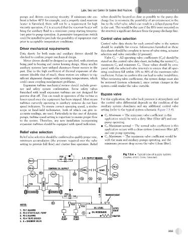
scope or hand-held tachometer, both of which can give in- setting (refer to the typical system schematic Figure 7.5.4).
accurate readings, are used. Particularly in the case of dynamic - C v Minimum e The minimum valve coefficient in this
pumps, turbine speed setting is important to ensure proper flow application would be with a dirty filter (filter DP) and one
to the system. Therefore, any new installation incorporating pump operating.
expansion turbines should be equipped with speed indication.
- C v Maximum normal e The normal valve coefficient in this
application occurs with a clean system (minimum filter DP)
Relief valve selection and one pump operating.
Relief valve selection should be confirmed to qualify proper size, - C v Maximum e The maximum valve coefficient would be
minimum accumulation (the pressure required over the valve with the main and auxiliary pumps operating, and the
setting to provide full flow) and chatter free operation. Relief minimum pressure drop across the valve (clean filter).
Fig 7.5.4 Typical lube oil supply system
(Courtesy of M.E. Crane, Consultant)
355