
Page 441 - Subyek Teknik Mesin - Forsthoffers Best Practice Handbook for Rotating Machinery by William E Forsthoffer
P. 441
Be st Practice 7 .20 Lube, Seal and Control Oil System Best Practices
Best
Best
Best Practice 7.20Practice 7.20Practice 7.20
Continuously vent the non-operating cooler and filter by Lessons Learned
installing orificed return lines, and keep the transfer valve Unit trips experienced during cooler and/or filter transfers
bypass fill line opened to ensure warm-up of the cooler and are usually blamedona ‘deadspot’ inthe transfervalvewhen
filter prior to transfer, in cold climates, to prevent a unit in fact, cool static oil of high viscosity in the non-operating
shutdown on low oil pressure. cooler and/or filter caused the unit to trip on low oil pressure.
In cold climates (ambient temperatures below 15 C at any time of It should be noted that all types of transfer valves (six-way, ball
the year), cool, static oil in the non-operating cooler and filter will cause valve design, etc.) do not have a ‘dead spot’ that can cause an oil
a transient pressure drop when it is changed on-line. This action can system pressure drop when transferred.
cause critical equipment unit trips on low oil pressure when the aux-
iliary pump did not start, or did not start in time. Benchmarks
Requiring orificed vents on all coolers and filters, and keeping the
This best practice has been used since the mid-1990s, when unit trips
non-operating vent lines open as well as the cooler and filter fill lines, were experienced that were caused by a cooler and filter transfer to
will ensure that non-operating coolers and filters are always maintained cold, static oil. Since that time, all projects, with ambient temperatures
at the same temperature as the operating vessels, and are vented and below 15 C at any time of the year, have been required to have cooler
ready for a successful transfer. and filter vents, and P&IDs indicating that valves were in open condi-
Where a trip has been caused by the issue noted above, operating tion. All field auxiliary system audits also recommended this approach
procedures should be revised and orificed vents installed if required. when ambient temperatures could fall below 15 C.
B.P. 7.20. Supporting Material
Transfer valves
The function of the transfer valves in the auxiliary system are to
allow transfer from one bank of components (coolers, filters,
etc.) to the stand-by bank of components without significant
pressure pulsations being introduced into the system. In addi-
tion, transfer valves must be designed to positively shut off the
unused components to allow for maintenance while the system
is in operation.
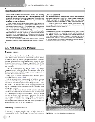
Types of transfer valves vary widely. Figure 7.20.1 shows
a six-port transfer valve that allows flow into the valve to be
diverted either to the left bank or right bank of components as
shown in the standard schematic.
Other types of transfer valves include the standard, globe-
type valve shown in Figure 7.20.2.
Both types exhibit the characteristic of minimal pressure
change when transferring from one bank to the other. The six-
ported valve should be designed with a lifting jack when a taper
plug is used. This feature allows transfer of valves from one bank
to another easily and still ensures tight shutoff of the valve when
in its proper position.
Selection of the valves should include material and sizing
considerations. Materials of construction should be carbon steel
as a minimum with stainless steel internals. The use of bronze
components should not be considered in systems that can in-
corporate gas entrained in the system fluid. In such systems
brass, copper or bronze is not permitted. Valves are sized to
match piping sizes in the system, which is normally designed for
fluid velocities of four to six feet per second.
Reliability considerations
As previously mentioned, transfer valves including lifting jacks
are susceptible to valve plug damage. Frequently, operators do Fig 7.20.1 6 port transfer valve (Courtesy of Hycoa)
412