
Page 445 - Subyek Teknik Mesin - Forsthoffers Best Practice Handbook for Rotating Machinery by William E Forsthoffer
P. 445
Be st Practice 7 .23 Lube, Seal and Control Oil System Best Practices
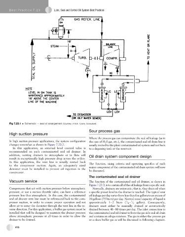
Fig 7.23.1 Schematic e seal oil arrangement (Courtesy of M.E. Crane, Consultant)
Sour process gas
High suction pressure
Where the process gas can contaminate the seal oil leakage (as in
In high suction pressure applications, the system configuration the case of H 2 S gas, etc.), the contaminated seal oil drain line is
changes somewhat as shown in Figure 7.23.2. usually routed to the plant contaminated oil system and not back
In this application, an external level control valve is to a degassing tank or the reservoir.
recommended on each contaminated seal oil drainer. In
addition, venting drainers to atmosphere or to flare will Oil drain system component design
result in exceptionally high pressure drop across the orifice.
In this application, the vent line is usually routed back The function, sizing criteria and operating specifics of each
to the compressor suction. Again, an adequately sized
demister must be installed to prevent oil ingestion in the major component of the contaminated oil drain system will now
be discussed.
compressor.
The contaminated seal oil drainer
Vacuum service The function of the contaminated seal oil drainer, as shown in
Figure 7.23.3, is to contain all of the oil leakage from a specificseal.
Compressors that act with suction pressure below atmospheric Normally, drainers are automatic; that is, they drain oil when
pressure, or use a suction throttle valve, can have a reference a specific preset level in the drainer is reached. The typical sour
pressure less than atmospheric. In this case, the contaminated oil leakage per day varies from less than five gallons to an excess of
seal oil drainer vent line must be referenced back to the com- 20 gallons (75 liters) per day. Normal vessel capacity of liquid is
1
1
pressor suction, in order to ensure proper operation and not approximately 1e2 liters ( / 4 / 2 gallon). Consequently,
allow air to enter the demister through the vent line in the re- drainers must either be manually drained or automatically
verse direction. For this application, a buffer gas system must be drained between 40e80 times per day. The inlet connection to
installed that will be designed to maintain the drainer pressure the contaminated seal oil drainer is from the gas side seal oil drain
above atmospheric pressure at all times in order to allow the and contains an oil-gas mixture. The gas is either the process gas
drainer to be drained. or a clean buffer gas as will be discussed in following chapters.
416