
Page 447 - Subyek Teknik Mesin - Forsthoffers Best Practice Handbook for Rotating Machinery by William E Forsthoffer
P. 447
Be st Practice 7 .23 Lube, Seal and Control Oil System Best Practices
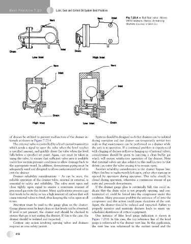
Fig 7.23.4 Ball float valve. Above:
WKM drainers; Below: Armstrong
drainers (Courtesy of Elliott Co.)
of drainer be utilized to prevent malfunction of the drainer in- Systems should be designed such that drainers can be isolated
ternals as shown in Figure 7.23.4. during operation and one drainer can temporarily service two
The external valve is controlled by a level control transmitter seals so that maintenance can be performed on a drainer while
which sends a signal to open the valve when the level reaches the unit is in operation. If a continued problem is experienced
a specified amount, and quickly closes the valve when the level with clogging of drainer orifices or hanging up of internal valves,
falls below a specified set point. Again, care must be taken in consideration should be given to injecting a clean buffer gas
sizing the valve, to ensure that sufficient valve area is available which will ensure satisfactory operation of the drainer. Note
under low suction pressure conditions to allow drainage back to that external valves are also subject to this malfunction in that
the appropriate vessel. In addition, downstream piping must be debris can enter the valve causing it to remain open.
adequately sized and designed to allow contaminated seal oil to Another reliability consideration is the drainer bypass line.
exit the drainer. Often this line is inadvertently left open, either after start-up or
Drainer reliability considerations e As can be seen, the opened by operators during operation. This valve should be
reliable operation of the drainer valve, internal or external, is closed during operation, otherwise a continuous stream of gas
essential to safety and reliability. The valve must open and exits and proceeds downstream.
close tightly upon signal to ensure a minimum amount of If the drainer gauge glass is continually full, this could in-
processed gas exits the drainer. Many applications process a gas dicate that the drain valve is not properly opening, and con-
that tends to be sticky or has a high amount of carbon that will taminated oil could be forced into the compressor under this
cause internal valves to bind, thus keeping the valve open at all condition. Many processes prohibit the entrance of oil into the
times. compressor and this action could cause shutdown of the unit.
Attention must be paid to the gauge glass on the drainer. Again, the drainer should be isolated and inspected. Failure to
Gauge glasses must be kept clean so that levels can be observed. properly monitor and maintain drainers leads to many un-
If level is not present, the drainer exit should be checked to scheduled shutdowns of critical equipment.
ensure that gas is not exiting the drainer. If this is the case, the One instance of false level gauge indication is shown in
drainer should be isolated and inspected. Figure 7.23.6. In this case, the top reference line of the level
Caution: any action involving opening valves and drainers gauge is referenced to the drainer vent line. In this application,
requires an area safety permit. the vent line was referenced to the suction vessel and the
418