
Page 449 - Subyek Teknik Mesin - Forsthoffers Best Practice Handbook for Rotating Machinery by William E Forsthoffer
P. 449
Be st Practice 7 .23 Lube, Seal and Control Oil System Best Practices
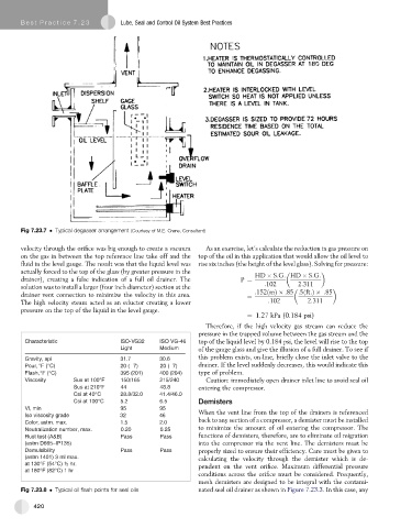
Fig 7.23.7 Typical degasser arrangement (Courtesy of M.E. Crane, Consultant)
velocity through the orifice was big enough to create a vacuum As an exercise, let’s calculate the reduction in gas pressure on
on the gas in between the top reference line take off and the top of the oil in this application that would allow the oil level to
fluid in the level gauge. The result was that the liquid level was rise six inches (the height of the level glass). Solving for pressure:
actually forced to the top of the glass (by greater pressure in the
HD S:G: HD S:G:
drainer), creating a false indication of a full oil drainer. The P ¼
solution was to install a larger (four inch diameter) section at the :102 2:311
drainer vent connection to minimize the velocity in this area. ¼ :152ðmÞ :85 :5ðft:Þ :85
The high velocity steam acted as an eductor creating a lower :102 2:311
pressure on the top of the liquid in the level gauge.
¼ 1.27 kPa (0.184 psi)
Therefore, if the high velocity gas stream can reduce the
pressure in the trapped volume between the gas stream and the
C h a r a c i t s i r e t c S I O - V G 3 2 ISO VG-46 top of the liquid level by 0.184 psi, the level will rise to the top
Light Medium of the gauge glass and give the illusion of a full drainer. To see if
G a r , y t i v a i p 3 7 . 1 3 6 . 0 this problem exists, on-line, briefly close the inlet valve to the
Pour, °F (°C) 2 0 ( 7) 20 ( 7) drainer. If the level suddenly decreases, this would indicate this
Flash, °F (°C) 3 9 5 2 ( 0 ) 1 4 0 0 2 ( 0 ) 4 type of problem.
Viscosity Sus at 100°F 150/165 215/240 Caution: immediately open drainer inlet line to avoid seal oil
Sus at 210°F 44 48.8 entering the compressor.
Csi at 40°C 28.8/32.0 41.4/46.0
Csi at 100°C 5.2 6.5 Demisters
, I V m n i 9 5 9 5
When the vent line from the top of the drainers is referenced
Iso viscosity grade 32 46
back to any section of a compressor, a demister must be installed
C , r o l o a t s m . m a x. 5 . 1 0 . 2
Neutralization number, max. 0.20 0.25 to minimize the amount of oil entering the compressor. The
Rust test (A&B) Pass Pass functions of demisters, therefore, are to eliminate oil migration
(astm D665–IP135) into the compressor via the vent line. The demisters must be
Demulsibility Pass Pass properly sized to ensure their efficiency. Care must be given to
(astm 1401) 3 ml max. calculating the velocity through the demister which is de-
at 130°F (54°C) ½ hr. pendent on the vent orifice. Maximum differential pressure
at 180°F (82°C) 1 hr
conditions across the orifice must be considered. Frequently,
mesh demisters are designed to be integral with the contami-
Fig 7.23.8 Typical oil flash points for seal oils nated seal oil drainer as shown in Figure 7.23.3. In this case, any
420