
Page 446 - Subyek Teknik Mesin - Forsthoffers Best Practice Handbook for Rotating Machinery by William E Forsthoffer
P. 446
Lube, Seal and Control Oil System Best Practices Best Practice 7 .23
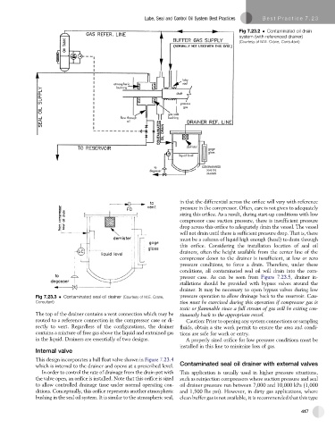
Fig 7.23.2 Contaminated oil drain
system (with referenced drainer)
(Courtesy of M.E. Crane, Consultant)
in that the differential across the orifice will vary with reference
pressure in the compressor. Often, care is not given to adequately
sizing this orifice. As a result, during start-up conditions with low
compressor case suction pressure, there is insufficient pressure
drop across this orifice to adequately drain the vessel. The vessel
will not drain until there is sufficientpressuredrop. That is, there
must be a column of liquid high enough (head) to drain through
this orifice. Considering the installation location of seal oil
drainers, often the height available from the center line of the
compressor down to the drainer is insufficient, at low or zero
pressure conditions, to force a drain. Therefore, under these
conditions, all contaminated seal oil will drain into the com-
pressor case. As can be seen from Figure 7.23.5, drainer in-
stallations should be provided with bypass valves around the
drainer. It may be necessary to open bypass valves during low
Fig 7.23.3 Contaminated seal oil drainer (Courtesy of M.E. Crane, pressure operation to allow drainage back to the reservoir. Cau-
Consultant)
tion must be exercised during this operation if compressor gas is
toxic or flammable since a full stream of gas will be exiting con-
The top of the drainer contains a vent connection which may be
tinuously back to the appropriate vessel.
routed to a reference connection in the compressor case or di- Caution: Prior to opening any system connections or sampling
rectly to vent. Regardless of the configurations, the drainer fluids, obtain a site work permit to ensure the area and condi-
contains a mixture of free gas above the liquid and entrained gas tions are safe for work or entry.
in the liquid. Drainers are essentially of two designs. A properly sized orifice for low pressure conditions must be
installed in this line to minimize loss of gas.
Internal valve
This design incorporates a ball float valve shown in Figure 7.23.4
which is internal to the drainer and opens at a prescribed level. Contaminated seal oil drainer with external valves
In order to control the rate of drainage from the drain pot with This application is usually used in higher pressure situations,
the valve open, an orifice is installed. Note that this orifice is sized such as reinjection compressors where suction pressure and seal
to allow controlled drainage time under normal operating con- oil drainer pressure run between 7,000 and 10,000 kPa (1,000
ditions. Conceptually, this orifice represents another atmospheric and 1,500 lbs psi). However, in dirty gas applications, where
bushing in the seal oil system. It is similar to the atmospheric seal, clean buffer gas is not available, it is recommended that this type
417