
Page 450 - Subyek Teknik Mesin - Forsthoffers Best Practice Handbook for Rotating Machinery by William E Forsthoffer
P. 450
Lube, Seal and Control Oil System Best Practices Best Practice 7 .23
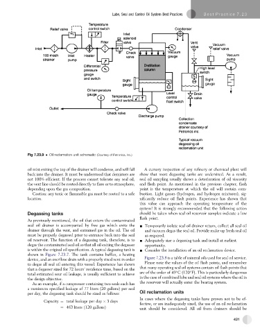
Fig 7.23.9 Oil reclamation unit schematic (Courtesy of Petronics, Inc.)
oil mist exiting the top of the drainer will condense, and will fall A cursory inspection of any refinery or chemical plant will
back into the drainer. It must be understood that demisters are show that most degassing tanks are undersized. As a result,
not 100% efficient. If the process cannot tolerate any seal oil, seal oil sampling usually shows a deterioration of oil viscosity
the vent line should be routed directly to flare or to atmosphere, and flash point. As mentioned in the previous chapter, flash
depending upon the gas composition. point is the temperature at which the oil will sustain com-
Caution: any toxic or flammable gas must be routed to a safe bustion. Light gasses (hydrogen, and hydrogen mixtures), sig-
location. nificantly reduce oil flash points. Experience has shown that
this value can approach the operating temperature of the
system! It is strongly recommended that the following action
Degassing tanks should be taken when seal oil reservoir samples indicate a low
flash point.
As previously mentioned, the oil that enters the contaminated
seal oil drainer is accompanied by free gas which exits the - Temporarily isolate seal oil drainer return, collect all seal oil
drainer through the vent, and entrained gas in the oil. The oil and vacuum degas the seal oil. Provide make up fresh seal oil
must be properly degassed prior to entrance back into the seal as required.
oil reservoir. The function of a degassing tank, therefore, is to - Adequately size a degassing tank and install at earliest
degas the contaminated seal oil so that all oil exiting the degasser opportunity.
is within the original oil specification. A typical degassing tank is - Consider the installation of an oil reclamation device.
shown in Figure 7.23.7. The tank contains baffles, a heating
device, and an overflow drain with a properly sized vent in order Figure 7.23.8 is a table of mineral oils used for seal oil service.
to degas all seal oil entering this vessel. Experience has shown Please note the values of the oil flash points, and remember
that a degasser sized for 72 hours’ residence time, based on the that many operating seal oil systems contain oil flash points that
are of the order of 49 C (120 F). This is particularly dangerous
total estimated sour oil leakage, is usually sufficient to achieve
the design objective. in the case of combined lube and seal oil systems where the oil in
As an example, if a compressor containing two seals each has the reservoir will actually enter the bearing system.
a maximum specified leakage of 77 liters (20 gallons) per seal
per day, the degassing tank should be sized as follows: Oil reclamation units
In cases where the degassing tanks have proven not to be ef-
Capacity ¼ total leakage per day 3 days
fective, or are inadequately sized, the use of an oil reclamation
¼ 463 liters ð120 gallonsÞ unit should be considered. All oil from drainers should be
421