
Page 454 - Subyek Teknik Mesin - Forsthoffers Best Practice Handbook for Rotating Machinery by William E Forsthoffer
P. 454
Lube, Seal and Control Oil System Best Practices Best Practice 7 .26
B Main pump unit - All instrumentation noted on attached list has
1. Acceptable pump and driver vibration been calibrated to specified values
2. Absence of cavitation - Steam lines to console blown
3. Pump and driver acceptable bearing temperature - Entire system vented
4. Driver governor and safety checks (uncoupled) if driver is
a steam turbine
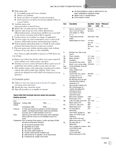
C Auxiliary pump unit Item Description Specified Actual Witnessed
Same procedure as item B above. value value by
D Relief valve set point and non-chatter check 1. Record reservoir temp. Record ______
E Operate main pump unit and confirm all pressures, rise in four (4) hours actual DT
differential pressures, temperatures and flows are as specified with heater on. Read
on the system schematic and/or bill of material on T.I.
F Confirm proper accumulator pre-charge (if applicable) 2. Check reservoir level High level High
switch
G Confirm proper set point annunciation and/or action of all setting Read on Annun. 14" from
pressure, differential pressure and temperature switches
top. low ______
H Switch transfer valves from bank ‘A’ to bank ‘B’ and confirm level
pressure fluctuation does not actuate any switches. 45" from Low
I Trip main pump and confirm auxiliary pump starts without top
actuation of any trip valves or valve instability. ______
3. Energize aux. lube pump
Note: Pressure spike should be a minimum of 30% above any check:
trip settings 3A. Pump vibration 0.2 in/sec ______
3B. Motor vibration 0.2 in/sec ______
J Repeat step I above but slowly reduce main pump speed (if 3C. Cavitation None ______
steam turbine) and confirm proper operation
3D. Pump/motor brg. temp 165 F ______
K Simulate maximum control oil transient flow requirement (if 4. Block in aux. pump using 3130 kPa ______
applicable) and confirm auxiliary pump does not start (see pump discharge valve-set
L Start auxiliary pump, with main pump operating and confirm note 1) relief valve
control valve and/or relief valve stability. Note: Some Valve chatter is not
systems are designed to not lift relief valves during two pump acceptable.
5. Confirm the ‘Aux. pump 690 kPa _____
operation
running’ Annun. is rising
actuated by switch
III Corrective action By shutting off pump and
restarting while reading
A Failure to meet any requirement in Section II requires pressure on PI
corrective action and retest 6. Allow system to heat up to
B Specifically note corrective action 49 C downstream of
C Sign-off procedure as acceptable to operate coolers and adjust the
following items (if
required) to attain
Typical initial field functional lube/seal system test procedure specified values:
baseline document 6A. Back press regulator 2262 _____
Read value on PI Kpa
Item: 6B. Lube oil supply valve PCV 124e138 _____
Reference Turbine utility P&ID _____ Read value on PI Kpa
DWGS: 6C. Control oil valve PCV 883
Compressor utility P&ID _____ Read value on PI Kpa _____
Purpose: To fully prove functional operation of entire lube/seal 6D. LP case seal oil 241
system, including all permissive, alarm and shutdown differential
functions prior to initial operation of the unit. valve PDCV. Supply N 2 Kpa _____
Note: All testing to be performed without the unit in operation. press, of 5 PSIG at gas
When specified values are not satisfied correct and reference
retest. side of PDT and read
Preparation: Prior to testing of the system, confirm and sign off that differential press on PDI
the following has been checked: 6E. HP case seal oil 241
- Oil reservoir at proper level differential
- Specified oil is used valve. Supply N 2 pressure kPa
- Oil heater in operation of 30 PSIG at gas
- Oil cooler water supply on reference side
- System clean (all test screens out) of PDT and read
- Instrument air in operation at all instruments differential press on PDI
- Temporary N 2 supply connected
(Continued)
425