
Page 494 - Subyek Teknik Mesin - Forsthoffers Best Practice Handbook for Rotating Machinery by William E Forsthoffer
P. 494
Lube, Seal and Control Oil System Best Practices Best Practice 7 .39
Best Practice 7.39Practice 7.39Practice 7.39
Best
Best
Oil bushing seals without a through-flow provision should It is true that during this time the differential across the inner (gas
have a false signal reference pressure, to ensure adequate side) bushing seal will be excessive, but this is a temporary condition
bushing flow to provide cooling for the seal during low that will not affect compressor operation.
process gas pressure conditions.
Since the flow through the atmospheric bushing is directly pro- Lessons Learned
portional to the reference gas pressure, low reference gas pressures Failure to provide sufficient seal oil pressure to the atmo-
during start-up will result in low cooling flow through the atmospheric spheric bushing during low reference gas pressure con-
bushing and corresponding bushing wear due to overheating. ditions exposes the atmospheric bushing to overheating
A means of ensuring the proper atmospheric bushing flow during and low MTBFs (less than 12 months).
low reference pressure conditions is to provide a false reference gas
signal via a pressure control valve and check valve arrangement in the Benchmarks
reference line to duplicate the pressure drop across the atmospheric
This best practice has been used since 1995; mostly as a recommen-
bushing during normal operating conditions.
dation to correct long term bushing seal low MTBFs, to maximize oil
seal reliability and to achieve oil seal MTBFs in excess of 100 months.
B.P. 7.39. Supporting Material
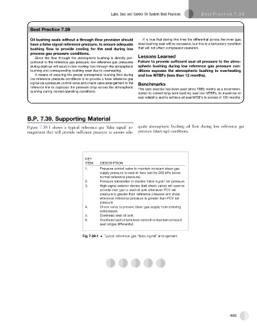
Figure 7.39.1 shows a typical reference gas ‘false signal’ ar- quate atmospheric bushing oil flow during low reference gas
rangement that will provide sufficient pressure to ensure ade- pressure (start-up) conditions.
KEY
ITEM DESCRIPTION
1. Pressure control valve to maintain constant clean gas
supply pressure to seal oil tank (set for 200 kPa below
normal reference pressure).
2. Pressure transmitter to monitor ‘false signal’ set pressure.
3. High signal selector device (ball check valve) will open to
provide inert gas to seal oil tank whenever PCV set
pressure is greater than reference pressure and close
whenever reference pressure is greater than PCV set
pressure.
4. Check valve to prevent clean gas supply from entering
compressor.
5. Overhead seal oil tank.
6. Overhead seal oil tank level controll to maintain constant
seal oil/gas differential.
Fig 7.39.1 Typical reference gas “false signal” arrangement
465