
Page 489 - Subyek Teknik Mesin - Forsthoffers Best Practice Handbook for Rotating Machinery by William E Forsthoffer
P. 489
Be st Practice 7 .36 Lube, Seal and Control Oil System Best Practices
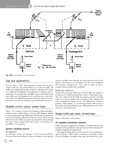
Fig 7.36.7 Dedicated 6P control buffer
Gas seal applications reactors, usually cannot tolerate any large amounts of oil in the
system. Oil carryover can necessitate an entire unit shutdown
Refer to Figure 7.36.6. This application ensures that the gas in and extensive cleaning time. Care must be taken to select
contact with the seal will be buffer gas. In this example, the a system that precludes this possibility.
buffer gas originates from the compressor discharge, but must Buffer gas reference
be conditioned and filtered (ten microns) to meet gas seal re- Systems incorporating buffer gas use the buffer gas supply as
quirements to preclude the possibility of gas seal passage foul- a reference for differential pressure control of the liquid seals.
ing. In this case, oil ingestion is not a problem since a gas seal is The valve selection of all buffer gas systems must be carefully
used. Also, the differential pressure does not need to be regu- made to prevent unstable valve operation. Valve hunting will
lated since the seal can withstand high differential pressures.
cause proportional swings of the seal differential reference
pressure. High swings, i.e., increasing pressure will result in
decreasing seal oil to reference gas differential pressure which
Multiple control valves, vented traps
can lead to unit shutdowns.
Figure 7.36.7 shows a design which utilizes a dedicated differ-
ential pressure control valve to each seal. This design is utilized Single buffer gas valve, vented traps
to ensure proper pressure differential (buffer gas to process gas)
at each seal. In this application, traps are vented which ensures Figure 7.36.8 shows this system.
a flow from the buffer gas system gas labyrinths down through
the traps. Proper sizing of the vent orifices can eliminate the Oil ingestion prevention systems
possibility of oil ingestion.
In the case that oil ingestion is prohibited, the following systems
can prevent the possibility of oil carryover into the compressor if
System reliability factors
properly designed and maintained.
Oil ingestion By properly sizing orifices in the vents of each contaminated
As mentioned above, oil ingestion can be a serious problem. seal oil drainer, a flow will be initiated to positively ensure
Processes that require dry gas, utilize exchangers, or incorporate all seal oil leakage is brought to the traps. Remember that in the
460