
Page 486 - Subyek Teknik Mesin - Forsthoffers Best Practice Handbook for Rotating Machinery by William E Forsthoffer
P. 486
Lube, Seal and Control Oil System Best Practices Best Practice 7 .36
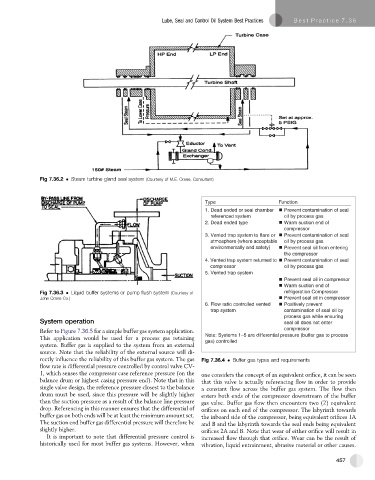
Fig 7.36.2 Steam turbine gland seal system (Courtesy of M.E. Crane, Consultant)
T y p e F u n o i t c n
1. Dead ended or seal chamber Prevent contamination of seal
referenced system oil by process gas
2. Dead ended type Warm suction end of
compressor
3. Vented trap system to flare or Prevent contamination of seal
atmosphere (where acceptable oil by process gas
environmentally and safety) Prevent seal oil from entering
the compressor
4. Vented trap system returned to Prevent contamination of seal
compressor oil by process gas
5. Vented trap system
Prevent seal oil in compressor
Warm suction end of
Fig 7.36.3 Liquid buffer systems or pump flush system (Courtesy of refrigeration Compressor
John Crane Co.) Prevent seal oil in compressor
6. Flow ratio controlled vented Positively prevent
trap system contamination of seal oil by
process gas while ensuring
System operation seal oil does not enter
Refer to Figure 7.36.5 for a simple buffer gas system application. compressor
This application would be used for a process gas retaining Note: Systems 1–5 are differential pressure (buffer gas to process
gas) controlled
system. Buffer gas is supplied to the system from an external
source. Note that the reliability of the external source will di-
rectly influence the reliability of this buffer gas system. The gas Fig 7.36.4 Buffer gas types and requirements
flow rate is differential pressure controlled by control valve CV-
1, which senses the compressor case reference pressure (on the one considers the concept of an equivalent orifice, it can be seen
balance drum or highest casing pressure end). Note that in this that this valve is actually referencing flow in order to provide
single valve design, the reference pressure closest to the balance a constant flow across the buffer gas system. The flow then
drum must be used, since this pressure will be slightly higher enters both ends of the compressor downstream of the buffer
than the suction pressure as a result of the balance line pressure gas valve. Buffer gas flow then encounters two (2) equivalent
drop. Referencing in this manner ensures that the differential of orifices on each end of the compressor. The labyrinth towards
buffer gas on both ends will be at least the minimum amount set. the inboard side of the compressor, being equivalent orifices 1A
The suction end buffer gas differential pressure will therefore be and B and the labyrinth towards the seal ends being equivalent
slightly higher. orifices 2A and B. Note that wear of either orifice will result in
It is important to note that differential pressure control is increased flow through that orifice. Wear can be the result of
historically used for most buffer gas systems. However, when vibration, liquid entrainment, abrasive material or other causes.
457