
Page 485 - Subyek Teknik Mesin - Forsthoffers Best Practice Handbook for Rotating Machinery by William E Forsthoffer
P. 485
Be st Practice 7 .36 Lube, Seal and Control Oil System Best Practices
Best Practice 7.36Practice 7.36Practice 7.36
Best
Best
Use clean, sweet, buffer gas whenever process gas is sour Lessons Learned
and/or can contain debris to optimize oil seal MTBF (in Failure to design for and use a sweet and clean buffer gas
excess of 120 months). in oil seal systems has resulted in low seal MTBFs (less
The entrance of sour gas and/or gas with debris into the oil seal than 12 months) and has caused gas releases in plants that
system will expose the seal oil system to the following issues that can have caused fires and personnel harm.
reduce seal MTBF, cause unscheduled shutdowns and pose a safety
I have known of a case of loss of life that was caused by an internal
hazard (gas release to the plant environment):
valve oil drainer remaining open in sour gas service, which released
Mechanical or iso carbon inner seal hang up and high seal oil H 2 S to the plant while an operator was checking seal oil leakage from
leakage this drainer.
Blockage of internal seal oil drainer orifices causing ingestion of seal
oil into the compressor Benchmarks
Contamination of overhead seal oil tanks with oil sludge, eventually
This best practice has been used and recommended for new projects
blocking internal seal oil ports and exposing the seals to low or zero and plant modifications, since the above incident occurred in the late
seal oil to gas differential and possible gas release to the plant
1970s, to ensure plant safety and optimize seal oil system reliability.
The use of a sweet and clean buffer gas will positively eliminate the
above problems to optimize the life of the seals and the reliability of the
seal system and corresponding unit (99.7% þ).
In this section, we will concentrate only on compressor buffer
B.P. 7.36. Supporting Material
systems.
The function of any buffer fluid system is to continuously supply
clean buffer fluid to each specified point at the required dif- Compressor buffer gas system overview
ferential pressure, temperature and flow rate. There are differ-
ent types of fluid buffer systems: Types of system
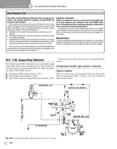
A. Compressor buffer systems (Figure 7.36.1) There are various types of compressor buffer gas systems for
B. Steam buffer systems (Figure 7.36.2) different applications. Refer to Figure 7.36.4 for a listing of
C. Liquid buffer systems or pump flush systems (Figure 7.36.3) system requirements.
Fig 7.36.1 Compressor buffer system (Courtesy of M.E. Crane, Consultant)
456