
Page 480 - Subyek Teknik Mesin - Forsthoffers Best Practice Handbook for Rotating Machinery by William E Forsthoffer
P. 480
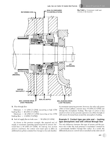
Lube, Seal and Control Oil System Best Practices  Best Practice 7 .34

                                                                                       Fig 7.34.9   Compressor shaft seal
                                                                                       (Courtesy of IMO Industries)


                                                                   At maximum operating pressure, however, the valve only passes
              3. Flow-through flow
                                                                   a flow of three gallons a minute since 46 LPM (12 GPM) exit
                Minimum ¼ 12 LPM (3 GPM) (occurring at high ATM
                                                                   through the atmospheric bushing. This type of system is less
              bushing flow ¼ 46 LPM [12 GPM])                       sensitive to low suction pressure operation since flow through oil
                Maximum ¼ 46 LPM (12 GPM) (occurring at low ATM    will remove frictional heat around the atmospheric bushing.
              bushing flow ¼ 12 LPM [3 GPM])
              4. Seal oil supply flow in both cases ¼ 58 LPM (15 GPM)  Example 2: Contact type gas side seal e bushing
                                                                   type atmospheric seal with orificed through flow
                As shown in the previous example, the required seal oil
              supply at maximum operating speed required to remove fric-  The only difference between this type of system and the pre-
              tional heat is 58 LPM (15 GPM). At start-up, low suction  vious one is that the back pressure is maintained constant by
              pressure conditions, the control valve must open to allow an  a permanently installed through flow orifice. As a result, the
              additional ten gallons a minute flow through to the seal chamber.  differential pressure control valve is installed on the inlet side of

                                                                                                               451