
Page 479 - Subyek Teknik Mesin - Forsthoffers Best Practice Handbook for Rotating Machinery by William E Forsthoffer
P. 479
Be st Practice 7 .34 Lube, Seal and Control Oil System Best Practices
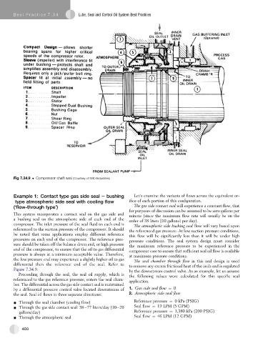
Fig 7.34.9 Compressor shaft seal (Courtesy of IMO Industries)
Example 1: Contact type gas side seal e bushing Let’s examine the variants of flows across the equivalent or-
type atmospheric side seal with cooling flow ifice of each portion of this configuration.
(‘flow-through type’) The gas side contact seal will experience a constant flow, that
for purposes of discussion can be assumed to be zero gallons per
This system incorporates a contact seal on the gas side and
minute (since the maximum flow rate will usually be on the
a bushing seal on the atmospheric side of each end of the order of 38 liters [10 gallons] per day).
compressor. The inlet pressure of the seal fluid on each end is
The atmospheric side bushing seal flow will vary based upon
referenced to the suction pressure of the compressor. It should the referenced gas pressure. At low suction pressure conditions,
be noted that some applications employ different reference this flow will be significantly less than it will be under high
pressures on each end of the compressor. The reference pres- pressure conditions. The seal system design must consider
sure should be taken off the balance drum end, or high pressure the maximum reference pressure to be experienced in the
end of the compressor, to ensure that the oil to gas differential compressor case to ensure that sufficient seal oil flow is available
pressure is always at a minimum acceptable value. Therefore, at maximum pressure conditions.
the low pressure end may experience a slightly higher oil to gas The seal chamber through flow in this seal design is used
differential then the reference end of the seal. Refer to to remove any excess frictional heat of the seals and is regulated
Figure 7.34.9.
by the downstream control valve. As an example, let us assume
Proceeding through the seal, the seal oil supply, which is the following values were calculated for this specific seal
referenced to the gas reference pressure, enters the seal cham-
application.
ber. The differential across the gas side contact seal is maintained
by a differential pressure control valve located downstream of 1. Gas side seal flow ¼ 0
the seal. Seal oil flows in three separate directions: 2. Atmospheric side seal flow
- Through the seal chamber (cooling flow) Reference pressure ¼ 0 kPa (PSIG)
- Through the gas side contact seal: 38e77 liters/day (10e20 Seal flow ¼ 19 LPM (5 GPM)
gallons/day) Reference pressure ¼ 1,380 kPa (200 PSIG)
- Through the atmospheric seal Seal flow ¼ 46 LPM (12 GPM)
450