
Page 477 - Subyek Teknik Mesin - Forsthoffers Best Practice Handbook for Rotating Machinery by William E Forsthoffer
P. 477
Be st Practice 7 .34 Lube, Seal and Control Oil System Best Practices
maintain the specified oil/gas differential under all operating
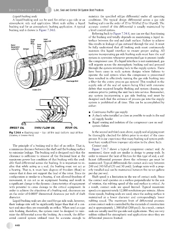
Liquid bushing seals
A liquid bushing seal can be used for either a gas side or an conditions. The typical design differential across a gas side
atmospheric side seal application. Most seals utilize a liquid bushing seal is on the order of 35 to 70 kPad (5 to 10 psid). The
bushing seal for an atmospheric bushing application. A typical accurate control of this differential is usually maintained by
bushing seal is shown in Figure 7.34.6. a level control system.
Referring back to Figure 7.34.6, one can see that functioning
of the bushing seal totally depends on maintaining a liquid in-
terface between the seal and shaft surface. Failure to achieve
this results in leakage of gas outward through the seal. It must
be fully understood that all bushing seals must continuously
maintain this liquid interface to ensure proper sealing. All
systems incorporating gas side bushing seals must have the seal
system in operation whenever pressurized gas is present inside
the compressor case. If a liquid interface is not maintained, gas
will migrate across the atmospheric bushing seal and proceed
through the system returning back to the supply system. There
have been cases in such system designs where failures to
operate the seal system when the compressor is pressurized
have resulted in effectively turning the gas side bushing into
a filter for the entire process gas system! This resulted in the
supply side of the seal oil system being filled with extensive
debris that required lengthy flushing and system cleaning op-
erations prior to putting the unit back into service. Remember,
any system incorporating a gas side bushing seal must be
designed such that the entrance of process gas into the supply
system is prohibited at all time. This can be accomplished by
either:
- Continuous buffer gas supply
- A check valve installed as close as possible to seals in the seal
oil supply header
- Rapid venting and isolation of the compressor case on seal
system failure
Fig 7.34.6 Bushing seal e top: oil film seal: bottom: seal oil flow In the second and third cases above, supply seal oil piping must
(Courtesy of Dresser-Rand) be thoroughly checked for debris prior to re-start of the com-
pressor. It is our experience that many bushing seal system prob-
lems have resulted from improper attention to the above facts.
The principle of a bushing seal is that of an orifice. That is, Contact seals
a minimum clearance between the shaft and the bushing surface Figure 7.34.7 shows a typical compressor contact seal. As
to minimize leakage. The bushing seal is designed such that the mentioned, these seals are similar in design to pump seals. In
clearance is sufficient to remove all the frictional heat at the order to remove the heat of friction for this type of seal, a suf-
maximum power loss condition of that bushing with the avail- ficient differential pressure above the reference gas must be
able fluid differential across the bushing. It is important to re- maintained. Typical differentials for contact seals vary between
alize that while acting as a seal, the bushing must not act as 240 and 345 kPad (35 and 50 psid). Leakage rates with a prop-
a bearing. That is, it must have degrees of freedom (float) to erly installed seal can be maintained between five to ten gallons
ensure that it does not support the load of the rotor. Since its per day per seal.
configuration is similar to a bearing, if not allowed freedom of Shaft speed is a limitation in the use of contact seals. Since
movement, it can act as an equipment bearing and result in the contact seal operates on a surface perpendicular to the axis
a significant change to the dynamic characteristics of equipment of rotation, the rubbing speed of the seal surface is critical. As
with potential to cause damage to the critical equipment. In a result, contact seals are speed limited. Typical maximum
order to achieve the objectives of a bushing seal, clearances are speeds are approximately 12,000 revolutions per minute. Above
on the order of 0.0005" diametrical clearance per inch of shaft those speeds, bushing seals are used, since the sealing surface is
diameter. maintained at a lower diameter and correspondingly lower
Liquid bushing seals are also used for gas side seals, however, rubbing speed. The maximum limit of differential pressure
their leakage rate will be significantly larger than that of a con- across contact seals is controlled by the materials of construction
tact seal since they are essentially an orifice. When used as a gas and is approximately 1,380 kPad (200 psid). As a result, contact
side bushing, therefore, the system must be designed to mini- seals are usually used for gas side seal applications. They are very
mize the differential across the bushing. As a result, the differ- seldom utilized for atmospheric seal applications since they are
ential control system utilized must be accurate enough to differential pressure limited.
448