
Page 482 - Subyek Teknik Mesin - Forsthoffers Best Practice Handbook for Rotating Machinery by William E Forsthoffer
P. 482
Lube, Seal and Control Oil System Best Practices Best Practice 7 .34
such a system, consideration should be given to a means of this configuration, the control valve which senses its signal from
changing the minimum flow and maximum flow orifice for the level transmitter, will be sized to continuously supply the
various operation points. Externally piped bypass orifices could required flow to maintain a constant level in the overhead tack.
be arranged such that a bypass line with a large orifice for As an example, consider the following system changes from
minimum suction pressure conditions could be installed and start-up to normal operation.
opened during this operation. It is important to note, however, In this example a change from the start-up to operating
that the entire supply system must be designed for this flow condition will increase gas reference pressure on the liquid level
condition and control valve must be sized properly to ensure in the overhead tank and would tend to push the level down-
proper flow at this condition. In addition, the low pressure ward. Any movement of the level in the tank will result in an
bypass line must be completely closed during normal high increasing signal to the level control valve to open, thus in-
pressure operation. creasing the pressure (assuming a positive displacement pump)
to the overhead tank and reestablishing the preset level.
Example 3: Bushing gas side seal e bushing In the above example, at 1,380 kPa (200 psi) reference
atmospheric side seal with no flow through pressure, the bypass valve would close considerably. To increase
provision the pressure supply of the seal oil from 34.5 to 1,410 kPa (5 to
205 psi), the difference of bypass flow through the valve 27
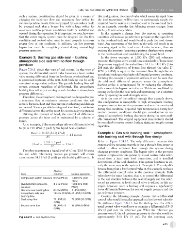
Figure 7.34.1 shows this type of seal system. In this type of LPM (7 GPM) is equal to the increased flow through the at-
system, the differential control valve becomes a level control mospheric bushing at this higher differential pressure condition.
valve sensing differential from the level in an overhead tank and Utilizing the concept of equivalent orifices, it can be seen that
is positioned upstream of the unit. Both bushings can be easily the additional differential pressure across the atmospheric
conceived as equivalent orifices. The gas side bushing flow will bushing orifice is compensated for by reducing the effective
remain constant regardless of differential. The atmospheric orifice area of the bypass control valve. This is accomplished by
bushing flow will vary according to seal chamber to atmospheric sensing the level in the head tank and maintaining it at a constant
pressure differential. value by opening the seal oil supply valve.
Therefore, the atmospheric bushing must be designed to pass
As in the case of the orificed through flow example above,
a minimum flow at minimum pressure conditions that will this configuration is susceptible to high atmospheric bushing
remove frictional heat and thus prevent overheating and damage
temperatures at low suction pressures and must be monitored
to the seal. Since a gas side bushing seal is utilized, a minimum during this condition. Repeated high temperatures during low
differential across this orifice must be continuously maintained. suction pressure conditions should give consideration to re-
Utilizing the concept of head, the control of differential sizing of atmospheric bushing clearances during the next avail-
pressure across the inner seal is maintained by a column of able turnaround. The original equipment manufacturer should
liquid. be consulted to ensure correct bushing sizing and supply system
As an example, if the required gas side seal differential of oil capability.
to gas is 34.5 kPad (5 psid) by the liquid head equation:
Head ¼ 0:102 ð34:5Þ kPadÞ Example 4: Gas side bushing seal e atmospheric
¼ 4:1 meters
:85 side bushing seal with through flow design
2:311 5 psid Refer to Figure 7.34.12. The only difference between this
Head ¼ ¼ 13:6ft: system and the previous example is that a through-flow option is
:85
added to allow sufficient flow through the system during
Therefore maintaining a liquid level of 4.1 m (13.6 ft) above
changing pressure conditions. The bypass valve in the previous
the seal while referencing process gas pressure will ensure system is replaced in this system by a level control valve refer-
a continuous 34.5 kPad (5 psid) gas side bushing differential. In
enced from a head tank level transmitter, and is installed
downstream of the seal chamber. This system functions in ex-
actly the same way as the system in Example 1. The only dif-
ference being that a level control valve in this example replaces
Start-up the differential control valve in the previous example. Both
Item condition Normal operation
valves have the same function, that is, to control the differential
Compressor suction pressure 0 kPa (PSIG) 1,380 kPa (200 in the seal chamber between the seal oil supply and the refer-
PSIG)
Overhead tank reference 0 kPa (PSIG) 1,380 kPa (200 enced gas pressure. A level control valve is utilized in this ex-
pressure PSIG) ample, however, since a bushing seal requires a significantly
lower differential between the seal oil supply pressure and the
Gas side seal bushing flow 0 LPM (GPM) 0 LPM (GPM)
Atmospheric side seal 19 LPM (5 GPM) 46 LPM (12 GPM) gas reference pressure.
bushing flow Consider the following example. Assume that a differential
Seal pump flow 77 LPM (20 77 LPM (20 GPM) control valve would be used as opposed to a level control valve for
GPM) the system in Figure 7.34.12. For the start-up case, the differ-
Bypass valve flow 58 LPM (15 31 LPM (8 GPM) ential control valve would have to maintain a differential of 34.5
GPM)
kPa (5 psi) over the reference gas. When the reference gas
pressure were 0, the oil upstream pressure to the valve would be
Fig 7.34.11 Seal System Flow approximately 34.5 kPa (5 psi). For the operating case,
453