
Page 487 - Subyek Teknik Mesin - Forsthoffers Best Practice Handbook for Rotating Machinery by William E Forsthoffer
P. 487
Be st Practice 7 .36 Lube, Seal and Control Oil System Best Practices
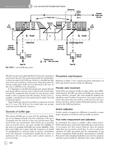
Fig 7.36.5 Typical buffer gas system
The flow on each end is then distributed back to the compressor Preventive maintenance
and towards the seal. This action ensures that the seal interface
is always in contact with buffer gas, which is a controlled gas that Referring to Figure 7.36.5, typical preventive maintenance of
meets unit seal cleanliness requirements. Depending upon the buffer gas systems should include the following:
oil trap configuration, buffer gas may flow back to the unit. In
this case, it will flow to the compressor.
It is important to note that this system only ensures that the Periodic valve movement
process gas will not come in contact with the seal. Greater flow Some buffer gas systems usually are quite stable, since differ-
towards the compressor than towards the sour oil traps could ential pressure of buffer gas valve and buffer gas opening can
result in seal oil ingestion into the machine. If this is not ac- remain relatively constant. The valve should be stroked peri-
ceptable, a modification to this system must be made. This will odically to ensure freedom of movement. Care must be taken to
be discussed below. ensure this action does not result in a unit trip since the com-
Typical buffer gas velocities towards the compressor end seal pressor seal oil or seal gas system differential pressure is refer-
are 6e9 m/sec (20e30 ft/sec) but should take into account enced to the buffer gas pressure.
maximum (worn) labyrinth clearances.
Switch calibration
Sources of buffer gas Periodic switch or transmitter calibration is essential to ensure
proper operation of all devices and acceptable set points.
The sources of buffer gas can vary with the application. Buffer
gas can be obtained directly from the compressor if the gas is
compatible with the seal oil, or from any external source that Flow meter measurement and calibration
meets buffer gas specifications. When buffer gas is provided As mentioned, the system is actually a flow control system.
from an external source, one must consider the reliability of Differential pressure control has historically been used because
the source in assessing total buffer gas system reliability. Note of its accuracy over flow control. However, there are systems
that when buffer gas is taken from the compressor, it should today that very accurately control flow. In order to assess the
be superheated to a sufficient value to prevent condensation operation of buffer gas system and the deterioration of any
across the labyrinth. Consideration should also be given to system components, buffer gas flow measurement is essential.
applications that are using water and/or solvent injection to Flow meter values should periodically be recorded by operators
prevent fouling. and flow meters should be calibrated. Flow meters should be
458