
Page 488 - Subyek Teknik Mesin - Forsthoffers Best Practice Handbook for Rotating Machinery by William E Forsthoffer
P. 488
Lube, Seal and Control Oil System Best Practices Best Practice 7 .36
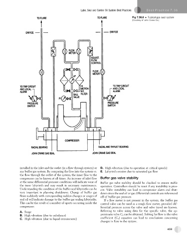
Fig 7.36.6 Typical gas seal system
(Courtesy of John Crane Co.)
installed in the inlet and the outlet (in a flow through system) or D. High vibration (due to operation at critical speeds)
any buffer gas system. By comparing the flow into the system vs. E. Labyrinth erosion due to saturated gas flow
the flow through the outlet of the system, the inner flow to the
compressor can be known at all times. An increase of inlet flow Buffer gas valve stability
at the same differential pressure conditions will indicate wear of Buffer gas valve stability should be checked to ensure stable
the inner labyrinth and may result in necessary maintenance. operation. Controllers should be reset if any instability is pres-
Understanding the condition of the buffer seal labyrinths can be ent. Valve instability can lead to compressor alarm and shut-
very important in planning shutdowns. Change of buffer gas down since the seal oil or gas differential controls are referenced
flows suddenly with corresponding sudden changes or usages of off of buffer gas pressure.
seal oil will indicate damage to the buffer gas sealing labyrinths. If a flow meter is not present in the system, the buffer gas
This can be the result of a number of upsets occurring inside the control valve can be used as a rough flow meter, provided dif-
compressor: ferential pressure across the valve and valve travel are known.
A. Surge Referring to valve sizing data for the specific valve, the ap-
B. High vibration (due to unbalance) proximate valve C v can be obtained. Solving for flow in the valve
C. High vibration (due to liquid entrainment) coefficient (C v ) equation can lead to conclusions concerning
changes in flow in the system.
459