
Page 492 - Subyek Teknik Mesin - Forsthoffers Best Practice Handbook for Rotating Machinery by William E Forsthoffer
P. 492
Lube, Seal and Control Oil System Best Practices Best Practice 7 .36
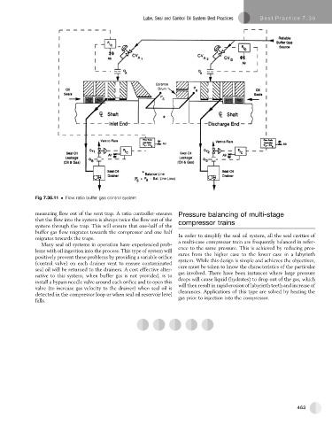
Fig 7.36.11 Flow ratio buffer gas control system
measuring flow out of the vent trap. A ratio controller ensures Pressure balancing of multi-stage
that the flow into the system is always twice the flow out of the compressor trains
system through the trap. This will ensure that one-half of the
buffer gas flow migrates towards the compressor and one half
migrates towards the traps. In order to simplify the seal oil system, all the seal cavities of
Many seal oil systems in operation have experienced prob- a multi-case compressor train are frequently balanced in refer-
lems with oil ingestion into the process. This type of system will ence to the same pressure. This is achieved by reducing pres-
positively prevent these problems by providing a variable orifice sures from the higher case to the lower case in a labyrinth
(control valve) on each drainer vent to ensure contaminated system. While this design is simple and achieves the objectives,
seal oil will be returned to the drainers. A cost effective alter- care must be taken to know the characteristics of the particular
native to this system, when buffer gas is not provided, is to gas involved. There have been instances where large pressure
install a bypass needle valve around each orifice and to open this drops will cause liquid (hydrates) to drop out of the gas, which
valve (to increase gas velocity to the drainer) when seal oil is will then result in rapid erosion of labyrinth teeth and increase of
clearances. Applications of this type are solved by heating the
detected in the compressor loop or when seal oil reservoir level
falls. gas prior to injection into the compressor.
463