
Page 491 - Subyek Teknik Mesin - Forsthoffers Best Practice Handbook for Rotating Machinery by William E Forsthoffer
P. 491
Be st Practice 7 .36 Lube, Seal and Control Oil System Best Practices
seal chamber, the leakage is atomized since the unit is operating. Warming systems
As a result, the velocity of the gas to the drain traps must be
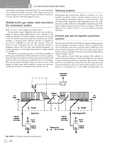
equal or greater than the velocity of gas towards the compressor Refrigeration gas compressors, ethylene, propylene, etc., fre-
to ensure all oil is drained through the traps. quently incorporate suction warming systems to prevent seal
cavity freeze-up. Discharge pressure is cycled directly to the
inlet side of the compressor. The temperature rise in the com-
Multiple buffer gas valves, vents returned to
pressor is usually sufficient to adequately warm this end of the
the compressor suction unit. A typical warming system is shown in Figure 7.36.10. Its
design is very similar to that of a gas seal system previously
Refer to Figure 7.36.9 which shows this system. discussed.
As previously stated, differential valves are used in this ex-
ample to ensure proper differential or (flow control) to the
buffer gas labyrinth. In addition, drainer trap vents are returned Process gas and oil ingestion preventive
to the compressor suction to avoid loss of process gas. In this systems
example, a properly sized, efficient demister is required to
prevent the possibility of any oil mist carryover from the We have previously discussed both process gas retaining systems
drainers to the compressor suction. The demister should be and oil ingestion preventive systems. There are applications
equipped with an oil level glass and checked frequently. In where both these systems are required, that is, buffer gas must
remote operations, a level alarm and automatic drainer should prevent both oil ingestion, and ensure the seal is not in contact
be installed. with process gas. An effective system to use in this application is
Oil ingestion prevention systems do offer the possibility of shown in Figure 7.36.11.
process gas contamination. If the velocity to the traps is greater The objective of any buffer gas system is flow-related. In
than the velocity towards the machine, process gas can be mixed order to meet the objective of ensuring buffer gas is in contact
with the buffer gas which can contaminate the seal oil leakage. with the seal and precluding oil ingestion, there must be equal
This type of system should incorporate periodic checks of oil gas flow in each direction; inward towards the compressor and
leakage (oil flash point and viscosity) to ensure that seal oil is outward towards the seal. The system shown achieves that ob-
within spec before it is returned to the seal oil reservoir. jective by measuring flow to the buffer gas labyrinths and
Fig 7.36.10 Typical compressor warming system
462