
Page 475 - Subyek Teknik Mesin - Forsthoffers Best Practice Handbook for Rotating Machinery by William E Forsthoffer
P. 475
Be st Practice 7 .34 Lube, Seal and Control Oil System Best Practices
cavity temperature is recommended during any off design (low
suction pressure condition) operation.
The seal housing system
Regardless of the type, the purpose of any seal is to contain the
fluid in the prescribed vessel (pump, compressor, turbine, etc.).
Types and designs of seals vary widely. Figure 7.34.3 shows
a typical mechanical seal used for a pump.
Since the contained fluid is a liquid, this seal utilizes that fluid
to remove the frictional heat of the seal and vaporize the liquid,
thus attaining a perceived perfect seal. A small amount of va-
porized liquid constantly exits the pump across the seal face. It
is a fact that all seals leak. This is the major reason that many
pump applications today are required to utilize seal-less pumps
to prevent emission of toxic vapors. The following is a discussion
of major types of seal combinations used in centrifugal com-
pressor seal applications.
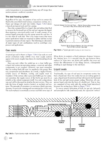
Gas seals Fig 7.34.4 Typical gas seal (Courtesy of John Crane Co.)
A typical gas seal is shown in Figure 7.34.4. Gas seals are used
almost exclusively today (2010) since their supply systems lifting device to maintain a fixed minimum clearance between
appear to be much simpler than those of a traditional liquid seal the rotating faces. It is essential that the gas between these
system. surfaces be clean since any debris will quickly clog areas and
Since gas seals utilize the sealed gas or a clean buffer gas, reduce the effectiveness of the lifting devices, consequently
a liquid seal system incorporating pumps, a reservoir and other resulting in rapid damage to the seal faces.
components, is not required. However, one must remember
that the sealing fluid still must be supplied at the proper flow Liquid seals
rate, temperature and cleanliness. As a result, a highly efficient,
reliable source of filtration, cooling, and supply must be Traditionally, the type of seal used in compressor service has
furnished. If the system relies upon inert buffer gas for contin- been a liquid seal. Since the media that we are sealing against is
ued operation, the supply source of the buffer gas must be as a gas, a liquid must be introduced that will remove the frictional
reliable as the critical equipment itself. Gas seal configurations heat of the seal and ensure proper sealing. Therefore, all com-
vary and will be discussed in detail in the next section. They can pressor liquid seals take the form of a double seal. That is, they
take the form of single, tandem (series), or multiple seal sys- are comprised of two seals with the sealing liquid introduced
tems. The principle of operation is to maintain a fixed minimum between the sealing faces. Refer to Figure 7.34.5.
clearance between the rotating and non-rotating face of the seal. To ensure proper lubrication of both the gas side (inboard)
The seal employed is essentially a contact seal with some type of and atmospheric side (outboard) seals, the equivalent ‘orifices’
Fig 7.34.3 Typical pump single mechanical seal
446