
Page 583 - Subyek Teknik Mesin - Forsthoffers Best Practice Handbook for Rotating Machinery by William E Forsthoffer
P. 583
Be st Practice 1 0.11 The Post-Shipment Phase: Installation, Pre-Commissioning, Commissioning and Start-up Best Practices
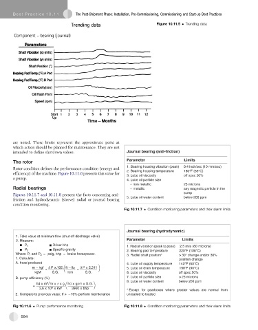
Figure 10.11.5 Trending data
are noted. These limits represent the approximate point at
which action should be planned for maintenance. They are not
intended to define shutdown values. Journal bearing (anti-friction)
Parameter Limits
The rotor
1. Bearing housing vibration (peak) 0.4 inch/sec (10 mm/sec)
Rotor condition defines the performance condition (energy and 2. Bearing housing temperature 180° F (85°C)
efficiency) of the machine. Figure 10.11.6 presents this value for
3. Lube oil viscosity off spec 50%
a pump. 4. Lube oil particle size
non metallic 25 microns
Radial bearings m c i l l a t e a n y m a g n c i t e p e l c i t r a n i h t e
Figures 10.11.7 and 10.11.8 present the facts concerning anti- 5. Lube oil water content sump
below 200 ppm
friction and hydrodynamic (sleeve) radial or journal bearing
condition monitoring.
Fig 10.11.7 Condition monitoring parameters and their alarm limits
Journal bearing (hydrodynamic)
1. Take value at minimum flow (shut off discharge valve)
2. Measure: Parameter Limits
Driver bhp
P 1 1. Radial vibration (peak to peak) 2.5 mils (60 microns)
P 2 Specific gravity 2. Bearing pad temperature 220°F (108°C)
Where: P 1 and P 2 = psig, bhp = brake horsepower. 3. Radial shaft position* > 30° change and/or 30%
1. Calculate: position change
A. head produced 4. Lube oil supply temperature 140°F (60°C)
m kgf Px.102 ft lb f Px2.311 5. Lube oil drain temperature 190 ° F (90°C)
= =
kgM S.G. lbm S.G. 6. Lube oil viscosity off spec 50%
B. pump efficiency (%) 7. Lube oil particle size > 25 microns
8. Lube oil water content below 200 ppm
3
/
hd x m hr x x g hd x gpm x S.G.
=
6
3.6x 10 xkW 3960 x bhp
* Except for gearboxes where greater values are normal from
2. Compare to previous value; if > 10% perform maintenance unloaded to loaded
Fig 10.11.6 Pump performance monitoring Fig 10.11.8 Condition monitoring parameters and their alarm limits
554