
Page 579 - Subyek Teknik Mesin - Forsthoffers Best Practice Handbook for Rotating Machinery by William E Forsthoffer
P. 579
Be st Practice 1 0.9 The Post-Shipment Phase: Installation, Pre-Commissioning, Commissioning and Start-up Best Practices
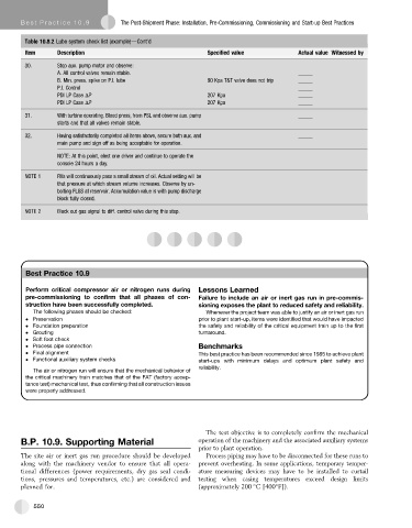
Table 10.8.2 Lube system check list (example)dCont'd
Item Description Specified value Actual value Witnessed by
30. Stop aux. pump motor and observe:
A. All control valves remain stable. _____
B. Min. press. spike on P.I. lube 90 Kpa T&T valve does not trip _____
P.I. Control _____
PDI LP Case DP 207 Kpa _____
PDI LP Case DP 207 Kpa _____
31. With turbine operating. Bleed press, from PSL and observe aux. pump _____
starts and that all valves remain stable.
32. Having satisfactorily completed all items above, secure both aux. and _____
main pump and sign off as being acceptable for operation.
NOTE: At this point, elect one driver and continue to operate the
console 24 hours a day.
NOTE 1 RVs will continuously pass a small stream of oil. Actual setting will be
that pressure at which stream volume increases. Observe by un-
bolting FLGS at reservoir. Accumulation value is with pump discharge
block fully closed.
NOTE 2 Block out gas signal to diff. control valve during this step.
Best Practice 10.9Practice 10.9Practice 10.9
Best
Best
Perform critical compressor air or nitrogen runs during Lessons Learned
pre-commissioning to confirm that all phases of con- Failure to include an air or inert gas run in pre-commis-
struction have been successfully completed. sioning exposes the plant to reduced safety and reliability.
The following phases should be checked: Whenever the project team was able to justify an air or inert gas run
Preservation prior to plant start-up, items were identified that would have impacted
Foundation preparation the safety and reliability of the critical equipment train up to the first
Grouting turnaround.
Soft foot check
Process pipe connection Benchmarks
Final alignment This best practice has been recommended since 1985 to achieve plant
Functional auxiliary system checks start-ups with minimum delays and optimum plant safety and
reliability.
The air or nitrogen run will ensure that the mechanical behavior of
the critical machinery train matches that of the FAT (factory accep-
tance test) mechanical test, thus confirming that all construction issues
were properly addressed.
The test objective is to completely confirm the mechanical
B.P. 10.9. Supporting Material operation of the machinery and the associated auxiliary systems
prior to plant operation.
The site air or inert gas run procedure should be developed Process piping may have to be disconnected for these runs to
along with the machinery vendor to ensure that all opera- prevent overheating. In some applications, temporary temper-
tional differences (power requirements, dry gas seal condi- ature measuring devices may have to be installed to curtail
tions, pressures and temperatures, etc.) are considered and testing when casing temperatures exceed design limits
planned for. (approximately 200 C [400 F]).
550