
Page 597 - Subyek Teknik Mesin - Forsthoffers Best Practice Handbook for Rotating Machinery by William E Forsthoffer
P. 597
Preventive and Predictive Maintenance Best Practices Best Practice 1 1.5
actuator failure, the control valve should be designed for on-line maintenance, an operator should be constantly present
isolation and bypass while on-line. to monitor and modulate the control valve manual bypass as
This design will permit valve or actuator change out without required.
shutting down the critical equipment. During control valve
Best Practice 11.5
Use the results of the plant component condition moni- Try to extend maintenance activity to the turnaround e discuss with
toring program (PDM) to extend oil lubricated coupling PM site vibration specialist, vendor and operations to determine action
maintenance intervals. plan
Many plants have a PM (preventive maintenance) procedure
in place for the yearly inspection and cleaning of oil lubricated Lessons Learned
couplings. Yearly inspection of oil lubricated couplings exposes the
This activity is usually unnecessary at these intervals, and can be plant to unnecessary shutdowns.
extended or postponed to a turnaround by reviewing the vibration Recent (2010) involvement with a site root cause failure analysis for
trends and frequency trends of the PDM program (vibration monitoring a steam turbine overspeed incident required a review of all of the
program). predictive (condition based) and preventive (time based) maintenance
We recommend the following procedure for extension of lubricated procedures with the affected train. An oil lubricated gear coupling was
coupling inspection intervals: installed and had a yearly PM for inspection and cleaning. Review of
Review the overall vibration and vibration frequency trends prior to vibration information, which did not show any significant change, led
the yearly oil lubricated coupling inspection the recommendation of this best practice. The recommendation was
Inspect and clean the coupling as required by the procedure accepted.
Observe the overall vibration and vibration frequency trend after
start-up Benchmarks
If the vibration trends are not different, continue to trend the This best practice has been recommended since the late 1980s to
coupling vibration and perform the next coupling inspection on result in extended, and in most cases postponed, oil lubricated gear
a condition basis (vibration values reach or exceed alarm setting) coupling inspections until the next turnaround.
B.P. 11.5. Supporting Material assemblies or mounted on each end of the coupling spacer
assembly. If the internal gears are hub-mounted, then the
external gears are spacer mounted and vice-versa.
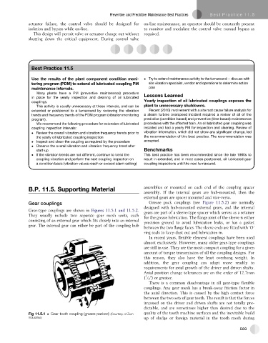
Gear couplings Grease pack couplings (see Figure 11.5.2) are normally
designed with hub-mounted external gears, and the internal
Gear-type couplings are shown in Figures 11.5.1 and 11.5.2. gears are part of a sleeve-type spacer which serves as a retainer
They usually include two separate gear mesh units, each for the grease lubrication. The flange joint of the sleeve is either
consisting of an external gear which fits closely into an internal precision ground to avoid lubrication leaks, or has a gasket
gear. The internal gear can either be part of the coupling hub
between the two flange faces. The sleeve ends are fitted with ‘O’
ring seals to keep dust out and lubrication in.
In recent years, flexible element couplings have been used
almost exclusively. However, many older gear-type couplings
are still in use. They are the most compact coupling for a given
amount of torque transmission of all the coupling designs. For
this reason, they also have the least overhung weight. In
addition, the gear coupling can adapt more readily to
requirements for axial growth of the driver and driven shafts.
Axial position change tolerances are on the order of 12.7mm
1
( / 2 ") or greater.
There is a common disadvantage in all gear-type flexible
couplings. Any gear mesh has a break-away friction factor in
the axial direction. This is caused by the high contact force
between the two sets of gear teeth. The result is that the forces
imposed on the driver and driven shafts are not totally pre-
dictable, and are sometimes higher than desired due to the
quality of the tooth machine surfaces and the inevitable build
Fig 11.5.1 Gear tooth coupling (grease packed) (Courtesy of Zurn
Industries) up of sludge or foreign material in the tooth mesh during
569