
Page 598 - Subyek Teknik Mesin - Forsthoffers Best Practice Handbook for Rotating Machinery by William E Forsthoffer
P. 598
Be st Practice 1 1.5 Preventive and Predictive Maintenance Best Practices
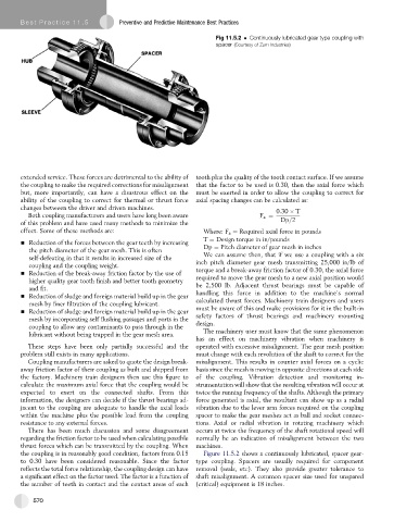
Fig 11.5.2 Continuously lubricated gear type coupling with
spacer (Courtesy of Zurn Industries)
extended service. These forces are detrimental to the ability of tooth plus the quality of the tooth contact surface. If we assume
the coupling to make the required corrections for misalignment that the factor to be used is 0.30, then the axial force which
but, more importantly, can have a disastrous effect on the must be exerted in order to allow the coupling to correct for
ability of the coupling to correct for thermal or thrust force axial spacing changes can be calculated as:
changes between the driver and driven machines. 0:30 T
Both coupling manufacturers and users have long been aware F a ¼
of this problem and have used many methods to minimize the Dp=2
effect. Some of these methods are: Where: F a ¼ Required axial force in pounds
T ¼ Design torque in in/pounds
- Reduction of the forces between the gear teeth by increasing
Dp ¼ Pitch diameter of gear mesh in inches
the pitch diameter of the gear mesh. This is often
self-defeating in that it results in increased size of the We can assume then, that if we use a coupling with a six
coupling and the coupling weight. inch pitch diameter gear mesh transmitting 25,000 in/lb of
- Reduction of the break-away friction factor by the use of torque and a break-away friction factor of 0.30, the axial force
required to move the gear mesh to a new axial position would
higher quality gear tooth finish and better tooth geometry
and fit. be 2,500 lb. Adjacent thrust bearings must be capable of
- Reduction of sludge and foreign material build up in the gear handling this force in addition to the machine’s normal
mesh by finer filtration of the coupling lubricant. calculated thrust forces. Machinery train designers and users
must be aware of this and make provisions for it in the built-in
- Reduction of sludge and foreign material build up in the gear
safety factors of thrust bearings and machinery mounting
mesh by incorporating self flushing passages and ports in the
design.
coupling to allow any contaminants to pass through in the
lubricant without being trapped in the gear mesh area. The machinery user must know that the same phenomenon
has an effect on machinery vibration when machinery is
These steps have been only partially successful and the operated with excessive misalignment. The gear mesh position
problem still exists in many applications. must change with each revolution of the shaft to correct for the
Coupling manufacturers are asked to quote the design break- misalignment. This results in counter axial forces on a cyclic
away friction factor of their coupling as built and shipped from basis since the mesh is moving in opposite directions at each side
the factory. Machinery train designers then use this figure to of the coupling. Vibration detection and monitoring in-
calculate the maximum axial force that the coupling would be strumentation will show that the resulting vibration will occur at
expected to exert on the connected shafts. From this twice the running frequency of the shafts. Although the primary
information, the designers can decide if the thrust bearings ad- force generated is axial, the resultant can show up as a radial
jacent to the coupling are adequate to handle the axial loads vibration due to the lever arm forces required on the coupling
within the machine plus the possible load from the coupling spacer to make the gear meshes act as ball and socket connec-
resistance to any external forces. tions. Axial or radial vibration in rotating machinery which
There has been much discussion and some disagreement occurs at twice the frequency of the shaft rotational speed will
regarding the friction factor to be used when calculating possible normally be an indication of misalignment between the two
thrust forces which can be transmitted by the coupling. When machines.
the coupling is in reasonably good condition, factors from 0.15 Figure 11.5.2 shows a continuously lubricated, spacer gear-
to 0.30 have been considered reasonable. Since the factor type coupling. Spacers are usually required for component
reflects the total force relationship, the coupling design can have removal (seals, etc). They also provide greater tolerance to
a significant effect on the factor used. The factor is a function of shaft misalignment. A common spacer size used for unspared
the number of teeth in contact and the contact areas of each (critical) equipment is 18 inches.
570