
Page 90 - Subyek Teknik Mesin - Forsthoffers Best Practice Handbook for Rotating Machinery by William E Forsthoffer
P. 90
Be st Practice 2 .12 Pump Best Practices
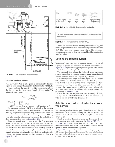
N SS NPSH R Inlet Inlet Probability of
velocity passage flow
ΔP separation
14,000 (High) Low Low Low High probability
8,000 (Low) High High High Low probability
Fig 2.12.18 N SS related to flow separation probability
The onset flow of recirculation increases with increasing suction
specific speed
Fig 2.12.19 Recirculation as a function of N SS
Which can also be stated as; ‘The higher the value of N SS , the
sooner the pump will cavitate when operating at flows below the
BEP’. Therefore, before an acceptable value of N SS can be de-
termined, the process system and pumped liquid characteristics
must be defined.
Defining the process system
Reviewing the proposed process system prior to the purchase of
a pump, as previously discussed, is strongly recommended.
Figure 2.12.20 presents a typical process system with various
control alternatives (flow, level, pressure).
The approach that should be followed when purchasing
Fig 2.12.17 Flange to vane entrance losses a pump is to define its required operating range on the basis of
the process system design and process requirements.
Once the operating range is defined, hydraulic calculations
Suction specific speed will determine the required flows, heads and NPSH AVAILABLE .
Care should be taken to define liquid composition and tem-
N SS , known as suction specific speed, is determined by the same
perature as accurately as possible, since these factors will de-
equation used for specific speed N S , but substitutes NPSH R for
H (pump head). As the name implies, N SS considers the inlet of termine the vapor pressure which in turn defines the
NPSH AVAILABLE . Steps for defining the process system are
the impeller and is related to the impeller inlet velocity. The
relationship for N SS is: summarized in Figure 2.12.21.
Once the process requirements are accurately defined,
p
N Q a pump can be selected that will meet these requirements
ffiffiffiffiffi
N SS ¼ 3=4 without the risk of hydraulic disturbances.
ðNPSH R Þ
Where: N ¼ speed
Q ¼ flow e GPM Selecting a pump for hydraulic disturbance
NPSH R ¼ Net Positive Suction Head Required in Ft. free service
As previously explained, NPSH R is related to the pressure
drop from the inlet flange to the impeller. The higher the The concepts used to prevent liquid disturbances, and the re-
NPSH R , the greater the pressure drop, and vice versa. From the quirements for accurately defining the process system re-
above equation, we can show the relationships between NPSH R , quirements, can then be used to select a pump free of hydraulic
N SS , inlet velocity, inlet pressure drop and the probability of disturbances.
flow separation. It is given in Figure 2.12.18. Based on previous discussions, there are three areas of con-
Based on this information, it can be seen that flow separation cern to ensure trouble-free operation (see Figure 2.12.22).
will occur for high specific speeds resulting from low inlet ve- Figure 2.12.23 shows a typical pump performance curve. The
locity. The critical question the pump user needs answered is practical approach is to select a type of pump that will enable
‘At what flow does the disturbance and resulting cavitation operation under all conditions if possible.
occur’? This is not easy to answer, because the unstable flow Figure 2.12.24 presents guidelines for selecting a pump free
range is a function of the impeller inlet design as well as the inlet of hydraulic disturbances, which attempt to cover all situations;
velocity. A general answer to this question is shown in however, technical discussions with the pump vendor are en-
Figure 2.12.19. couraged whenever necessary.
64