
Page 87 - Subyek Teknik Mesin - Forsthoffers Best Practice Handbook for Rotating Machinery by William E Forsthoffer
P. 87
Pump Best Practices Best Practice 2 .12
Fig 2.12.9 Recirculation flow pattern in impeller at low flows
Fig 2.12.10 Discharge recirculation flow pattern
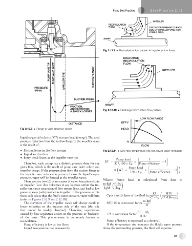
Fig 2.12.8 Flange to vane entrance losses
liquid tangential velocity (VT) increase head (energy). The total
pressure reduction from the suction flange to the impeller vanes
is the result of:
Friction losses in the flow passage Fig 2.12.11 Low flow temperature rise can cause vapor formation
Liquid acceleration
Entry shock losses at the impeller vane tips
Pump head 1
DT ¼ 1
Therefore, each pump has a distinct pressure drop for any 337; 100 C P Pump efficiency
given flow, which is the result of pump case, inlet volute and Pump head 1
impeller design. If the pressure drop from the suction flange to DT ¼ 1
778 C P Pump efficiency
the impeller vane reduces the pressure below the liquid’s vapor
pressure, vapor will be formed at the impeller vanes.
There are also two (2) other causes of vapor formation within Where: Pump head is calculated from data in
an impeller. Low flow velocities at any location within the im- m-kgf ft-lb f
peller can cause separation of flow stream lines, and lead to low kgM lb M
pressure areas (cells) inside the impeller. If the pressure within KJ BTU
these cells is less than the fluid’s vapor pressure, vapor will form Cp is specific heat of the fluid in
C kg F -LBmass
(refer to Figures 2.12.9 and 2.12.10). m-kgf
The curvature of the impeller vanes will always result in 367,100 is conversion factor
lower velocities on the pressure side of the vane (the side kJ
that cannot be readily observed). Therefore, vaporization
FT LB F
caused by flow separation occurs on the pressure or ‘backside’ 778 is conversion factor
of the vane. This phenomenon is commonly known as BTU
recirculation. Pump efficiency is expressed as a decimal.
Pump efficiency is low at low flows: If the temperature rise increases the fluid’s vapor pressure
Liquid temperature rise increases by above the surrounding pressure, the fluid will vaporize.
61