
Page 83 - Subyek Teknik Mesin - Forsthoffers Best Practice Handbook for Rotating Machinery by William E Forsthoffer
P. 83
Pump Best Practices Best Practice 2 .11
Define operating range of application Step Action
Accurately define liquid characteristics 1. Confirm NPSH A NPSH R at maximum operating flow. If margin
Vapor pressure less than two (2) feet, require witnessed NPSH R test. If NPSH R
Pumping temperature > NPSH :
A
Viscosity Increase NPSH A by:
Perform hydraulic calculations for all required flow rates to Increasing suction drum level
determine: Decreasing pumping temperature
Head required Decreasing suction line losses
NPSH AVAILABLE Reselect pump (if possible)
Select canned pump
2. For the pump selected calculate N SS based on pump BEP
Fig 2.11.2 Preventing liquid disturbances by accurately defining conditions. Note: if double suction first stage impeller, use 1/2
process requirements of BEP flow
3. If N SS > 8000, contact pump vendor and require following data
for actual pump fluid and conditions:
Predicted onset flow of cavitation caused by recirculation for
actual fluid conditions
Reference list of proposed impeller (field experience)
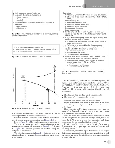
1. NPSH margin at maximum operating flow 4. Compare cavitation flow to minimum operating flow. If this
2. Approximate recirculation margin at minimum operating flow value is within 10% of minimum operating flow:
3. NPSH margin at minimum operating flow Reselect pump if possible
Install minimum flow bypass
Consider parallel pump operation
Fig 2.11.3 Hydraulic disturbances e areas of concern 5. Calculate liquid temperature rise at minimum operating flow. If
value is greater than 5% of pumping temperature:
Calculate NPSH A based on vapor pressure at calculated
pumping temperature. If NPSH A < NPSH :
R
Install minimum flow bypass
Consider parallel pump operation
Fig 2.11.5 Guidelines for selecting pumps free of hydraulic
disturbances
Before proceeding, an important question regarding the
typical pump performance curve needs to be asked. Why is
the NPSH R curve not drawn to zero flow like the head curve?
Based on the information presented in this course, you
should be able to answer this question. Consider the fol-
lowing facts:
- The standard shop test fluid for all pumps is water
- The causes of vaporization at low flows
Hopefully your answer took the following form:
‘Liquid disturbances can occur at low flows if the vapor
pressure of the pumped liquid exceeds the surrounding pressure
of the liquid.’
Fig 2.11.4 Hydraulic disturbance e areas of concern ‘Flow separation and/or liquid temperature rise which can
occur at low flows will either reduce the surrounding pressure
process system requirements, this information can be used to on a liquid or increase its vapor pressure.’
select a pump free of hydraulic disturbances. ‘Since the actual liquid characteristics are not known when
Based on previous discussions, there are three areas of con- the standard pump curve (tested on water) is drawn, the vendor
cern to ensure trouble-free operation (see Figure 2.11.3). stops the NPSH R curve where flow separation and liquid
Refer to Figure 2.11.4 for a typical pump performance curve. temperature rise can cause liquid disturbances.’
The practical approach is to select a type of pump that will Therefore, trouble free operation to the left of this point is
enable operation under all conditions in Figure 2.11.3 if possi- dependent on the pumped liquid and must be discussed with
ble. Figure 2.11.5 presents guidelines for selecting a pump free the pump vendor.
of hydraulic disturbances. In conclusion, preventing liquid disturbances at the project
The guidelines presented in Figure 2.11.5 attempt to cover all design phase requires a thorough, accurate investigation of both
situations; however, technical discussions with the pump vendor the process and pump characteristics and some serious decisions
is encouraged. on required action.
57