
Page 79 - Subyek Teknik Mesin - Forsthoffers Best Practice Handbook for Rotating Machinery by William E Forsthoffer
P. 79
Pump Best Practices Be st Practice 2.9
High flow operation
Selecting a pump to operate far to the right of best efficiency
point can also result in potential problems, as highlighted in
Figure 2.9.7.
Operation at high flows can result in:
High to overloading horsepower with reduced system resistance
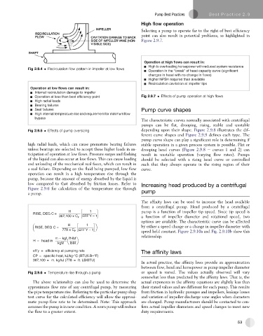
Fig 2.9.4 Recirculation flow pattern in impeller at low flows
Operation in the “break” of head capacity curve (significant
changes in head with no change in flows)
Higher NPSH required than available
Recirculation cavitation at impeller tips
Operation at low flows can result in:
Internal recirculation damage to impeller
Operation at less than best efficiency point Fig 2.9.7 Effects of pump operation at high flows
High radial loads
Bearing failures
Seal failures Pump curve shapes
High internal temperature rise and requirement for minimumflow
bypass
The characteristic curves normally associated with centrifugal
pumps can be flat,drooping,rising,stable and unstable
Fig 2.9.5 Effects of pump oversizing depending upon their shape. Figure 2.9.8 illustrates the dif-
ferent curve shapes and Figure 2.9.9 defines each type. The
pump curve shape can play a significant role in determining if
high radial loads, which can cause premature bearing failures stable operation in a given process system is possible. Flat or
unless bearings are selected to accept these higher loads in an- drooping head curves (Figure 2.9.8 e curves 1 and 2) can
ticipation of operation at low flows. Pressure surges and flashing result in unstable operation (varying flow rates). Pumps
of the liquid can also occur at low flows. This can cause loading should be selected with a rising head curve or controlled
and unloading of the mechanical seal faces, which can result in such that they always operate in the rising region of their
a seal failure. Depending on the fluid being pumped, low flow curve.
operation can result in a high temperature rise through the
pump, because the amount of energy absorbed by the liquid is
low compared to that absorbed by friction losses. Refer to Increasing head produced by a centrifugal
Figure 2.9.6 for calculation of the temperature rise through
a pump. pump
The affinity laws can be used to increase the head available
from a centrifugal pump. Head produced by a centrifugal
H 1 pump is a function of impeller tip speed. Since tip speed is
RISE, DEG C =
367,100 x C P EFF’Y – 1 a function of impeller diameter and rotational speed, two
options are available. The characteristic curve can be affected
H 1
RISE, DEG C = by either a speed change or a change in impeller diameter with
EFF’Y – 1
778 x C P speed held constant. Figure 2.9.10a and Fig. 2.9.10b show this
relationship.
m kgf ft-lbf
H = head in
kgM lbM
eff’y = efficiency at pumping rate
The affinity laws
CP = specific heat, kJ/kg-°C (BTU/LB–°F)
367,100 = m. kg/kJ (778 = ft. LB/BTU)
In actual practice, the affinity laws provide an approximation
between flow, head and horsepower as pump impeller diameter
Fig 2.9.6 Temperature rise through a pump or speed is varied. The values actually observed will vary
somewhat less than predicted by the affinity laws. That is, the
The above relationship can also be used to determine the actual exponents in the affinity equations are slightly less than
approximate flow rate of any centrifugal pump, by measuring their stated values and are different for each pump. This results
the pipe temperature rise. Referring to the particular pump shop from friction in hydraulic passages and impellers, leakage losses
test curve for the calculated efficiency will allow the approxi- and variation of impeller discharge vane angles when diameters
mate pump flow rate to be determined. Note: This approach are changed. Pump manufacturers should be contacted to con-
assumes the pump is in new condition. A worn pump will reduce firm actual impeller diameters and speed changes to meet new
the flow to a greater extent. duty requirements.
53